

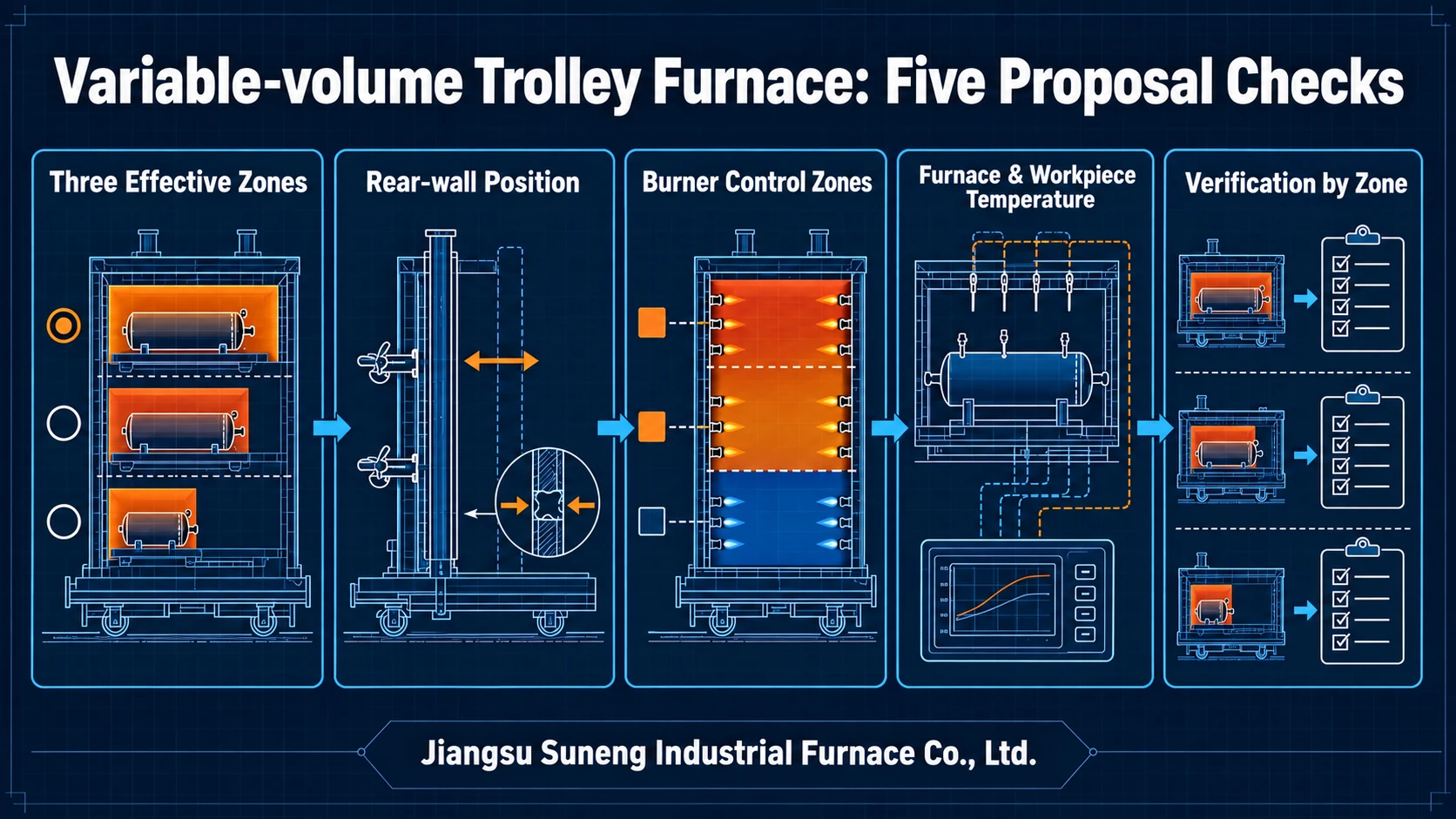
Review a variable-volume trolley furnace proposal for pressure vessels in five parts: rear wall and effective zone, burner control, seals, furnace/workpiece measurements and verification by zone. The historical Suneng proposal records three effective zones and their configuration. These records support procurement questions; configuration alone establishes neither a fixed saving nor the control and acceptance plan for a new project.
This article draws on Suneng's variable-volume gas-fired trolley-furnace proposal dated 27 April 2020. The proposal does not establish delivery or acceptance. The customer remains anonymous. Dimensions, loading, temperatures, zones and test figures below are the proposal's inputs and agreed targets; the article does not reproduce individual final test measurements or offer a universal configuration.
Which effective heating lengths does the proposal record?
The furnace was specified for post-weld stress relief of pressure vessels and other weldments. The physical chamber is 15.3 × 7.3 × 7.15 m, the door opening 7 × 7 m and the trolley deck 15 × 7 m. The proposed maximum load is 200 tonnes, excluding heat treatment support saddles.
The movable rear wall provides effective heating zones of 5 × 7 × 7 m, 10 × 7 × 7 m and 15 × 7 × 7 m, selected for the occupied workpiece length. Reduced heated space does not translate directly into a fixed saving: fuel use also depends on weight, material, starting temperature, curve, holding, utilisation, seals and metering boundary.
1. Rear-wall position and the corresponding effective zone
Check the recorded rear wall, trolley, sealing mechanisms and controls together. Match each wall position to its corresponding effective heating area. The movement method, seal structure and actuator quantities belong to this project and cannot be copied directly to other furnace dimensions.
2. Control documents for each effective zone
The gas-fired proposal specifies 12 burner assemblies and 12 furnace-temperature control zones. Request combustion and control descriptions for each effective-zone setting; burner count alone does not establish the active range. Check how the documents relate rear-wall position, combustion zones, doors, trolley, seals and safety interlocks. Operating permissions, switching and abnormal responses follow this equipment’s technical documents and controlled procedures. These are project quantities, not universal requirements.
3. Sealing descriptions for each rear-wall position
Match the 5 m and 10 m rear-wall positions separately to the proposal’s sealing descriptions. Ask the supplier to identify each position’s seal arrangement and verification conditions. A drawing for the maximum effective zone cannot replace descriptions for every position.
4. Furnace control and workpiece temperature records are different
The 12 furnace-temperature control zones are accompanied by 16 workpiece-thermocouple channels with display, recording and alarms. Furnace sensing controls the heating zones; workpiece sensing follows actual temperatures at selected locations. Sixteen channels is a project configuration, and point number and position require the workpiece, dimensions, layout, process and test method.
The historical proposal lists control-point accuracy as “±1°C” and the holding-temperature target as “≤±10°C (at or above 550°C)”, with measurement at the end of holding noted separately. These are proposal targets, not measured results. The 550°C threshold belongs to this proposal and is not a universal minimum survey temperature.
The proposal cited the 2012 method; this article explains the current method in GB/T 9452-2023. Correct readings for the sensor, compensation cable and instrument, then subtract the test-zone setpoint from each actual temperature. Compare the maximum and minimum deviations with the process limits. Highest-minus-lowest spread is not a substitute, and the “±1°C” control target does not establish work-zone uniformity. The survey must also meet data-collection and test-validity requirements; an end-of-hold reading or an average alone is insufficient. If a point fails the original process target, adjust and resurvey.
5. Effective zones and conditions covered by the report
GB/T 9452-2023 requires separate surveys for different qualified work zones. For the proposed 5 m, 10 m and 15 m settings, match each report to rear-wall position, active burner zones, seals and loading. Record test temperatures and setpoints, sensor positions, calibration corrections, sampling times, upper/lower deviations and conclusions for each setting. Records for the 15 m state alone do not establish temperature conformity for the other settings.
The original plan includes cold and hot commissioning, uniformity and energy-efficiency tests, followed by 1–2 trial-production batches. These describe the planned verification scope; no individual measured test values are supplied here. A new project can use the current method described above, with process tolerances and work zones specified in its technical agreement. The new edition does not retrospectively change the historical proposal or establish its acceptance.
Project parameters and boundaries
| Item | Proposal | Boundary |
|---|---|---|
| Workpieces | Pressure vessels and other weldments of varying sizes. | Post-weld stress relief, not every vessel treatment. |
| Effective zones | 5 m, 10 m and 15 m lengths; 7 × 7 m cross-section. | Specific trolley and rear-wall structure. |
| Maximum load | 200 tonnes excluding heat treatment support saddles. | Confirm load distribution, supports and rails. |
| Operating/design temperature | 800°C operating; 850°C maximum design. | Equipment parameters, not a recommended treatment temperature. |
| Furnace control | 12 burners and 12 zones. | Recalculate for another thermal duty. |
| Workpiece sensing | 16 channels with records and alarms. | Locate points for the workpiece and process. |
| Temperature targets | Control point ±1°C; source holding-temperature notation ≤±10°C at or above 550°C, measured at the end of holding. | Historical targets. Compare corrected survey readings with the test setpoint; an end-of-hold reading alone is insufficient. |
| Acceptance plan | Cold/hot commissioning, uniformity, efficiency and 1–2 trial batches. | Methods and criteria require project agreement. |
Supply responsibilities and enquiry inputs
In this project, Suneng is responsible for furnace design, manufacture, installation, cold/hot commissioning and inspection/testing, excluding civil foundations. The customer supplies foundations, building, utilities, low-voltage cable connection, gas conditions and fixtures. Other projects follow their own contracts.
Provide product, grade, dimensions, individual and total load, support saddles and layout, the batch mix by size, complete post-weld treatment curves, measurement requirements, utilities, building/foundation constraints and acceptance for each chamber state. Size mix and loading frequency directly affect whether variable volume is worthwhile.
Suneng can compare fixed and variable-volume trolley proposals and define the effective zones, wall/seals, burners, records and supply boundary. Final parameters follow the agreed technical documents.