
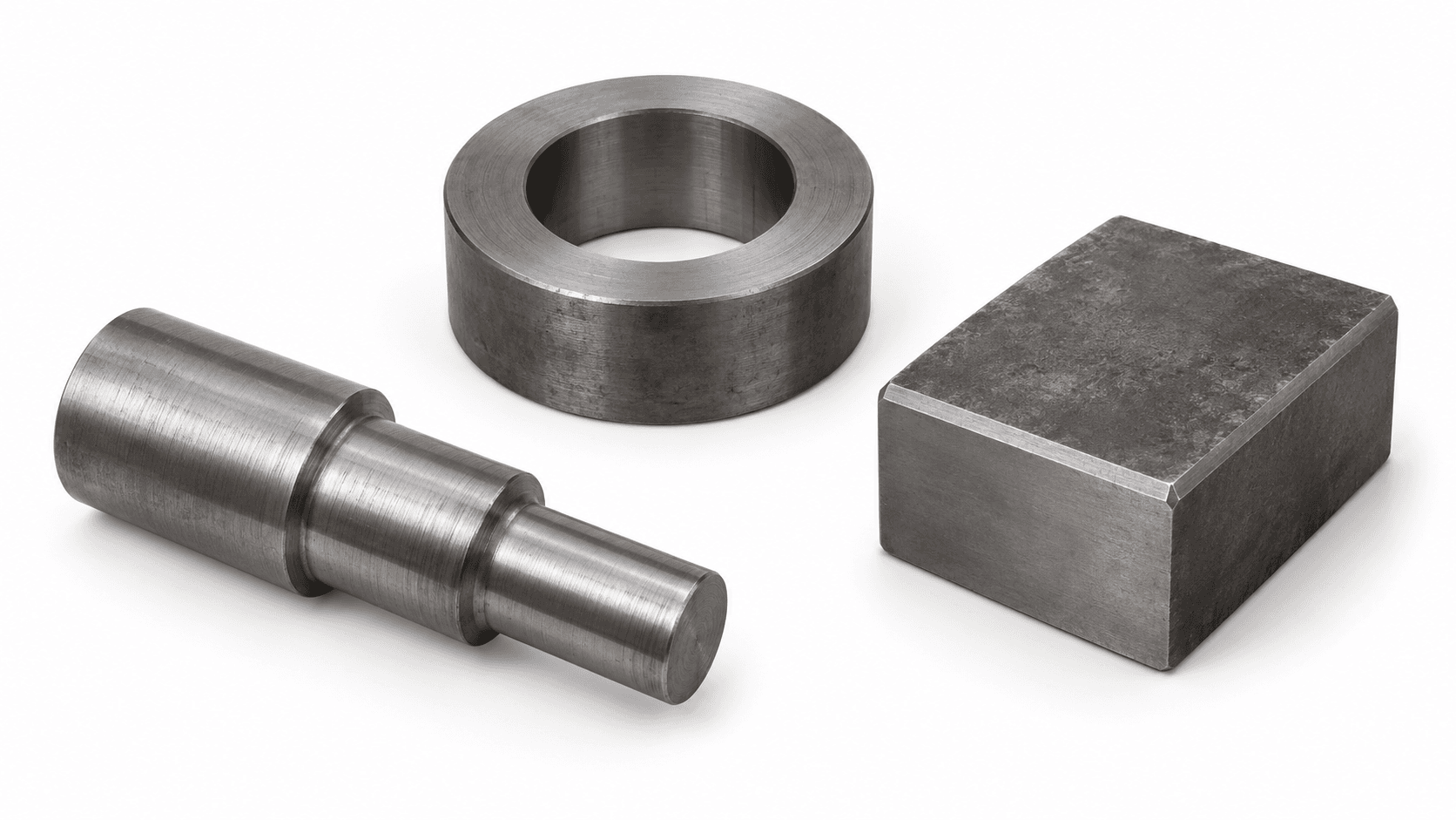
Workpieces & heat-treatment requirements
Shafts, rings and blocks are possible batch loads. Grade, section, incoming condition and target properties determine heating and quenching conditions.

Loading page…
Reload pageIndependent batch heating, with one manipulator loading and transferring by task
Coordinate independent heating furnaces, a shared manipulator and quench tank as one cell. Confirm furnace discharge windows, then check pick/place, travel and quench-entry cycles. Suitable for flexible batch scheduling; furnace and tank quantities and capacities depend on actual conditions.
Fitting parts into the furnace is only the first check. Verify tray support, maximum hot load, centre of gravity and each furnace discharge window so the manipulator can complete all handling and transfer movements.
Shafts, rings and blocks are possible batch loads. Grade, section, incoming condition and target properties determine heating and quenching conditions.

Include trays and fixtures in total mass. Check fork clearance, supports, centre of gravity and thermal distortion; shafts also need reliable restraint.
Sharing can be assessed where discharge windows can be staggered, the same medium and operating condition are suitable, and transfer capacity has sufficient margin. Batches requiring simultaneous discharge or incompatible media need separate organisation.
Point to equipment or select a step to see its location and action
Scroll horizontally for the complete line, or select a step below
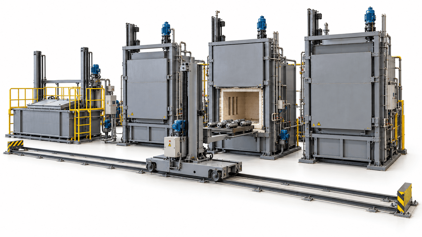
Transfer parts into the shared tank and quench under controlled material and process conditions.
Equipment: Shared quench tank
Each furnace heats independently while the manipulator travels between assigned tasks. The equipment illustration and batch sequence describe different aspects; parts do not pass through every furnace in turn.
Agree transfer timing events and limits against material and the adopted specification, covering required door opening, pickup, travel and tank entry. Where tempering is needed, also confirm equipment, permitted post-quench interval and transfer interfaces.
Do not simply add individual furnace capacities. Coordinate heating completion, manipulator availability and tank readiness. Define load holding, safe stopping and recovery before abnormal situations arise.
Highlights identify functional areas. Equipment and layout follow the agreed proposal.
First define how equipment connects, then discuss furnace count, loading and production rhythm.
Scroll horizontally to view the complete comparison
| Configuration item | Equipment & interface requirements |
|---|---|
| Independent heating furnaces | Select chamber, heat source, temperature control and doors against parts and process. Standardise or individually check loading heights, door clearance and discharge permissions. |
| Manipulator & rails | Check total load, centre of gravity, travel, lift and fork extension, positioning and thermal protection. Require confirmed fork retraction before travel along the shared route. |
| Trays & fixtures | Define support points, pickup datums, fork access, heat-resistant condition and thermal-distortion allowances to prevent slipping and handling interference. |
| Shared quench tank | Check medium compatibility, entry method, batch heat input, circulating heat exchange and tank occupation. Coordinate covers, lifting and handling movements. |
| Scheduling & interlocks | Coordinate doors, fork position, location, tank availability, level/temperature and other required states. Reserve resources by process priority and discharge window. |
| Personnel protection & recovery | Define segregation, door locking, detection and safety controls from risk assessment. Specify power-loss holding, controlled recovery and restart conditions. |
Before adding furnaces, recheck the complete manipulator cycle and tank occupation. Controller or inverter brands do not replace safety-function verification.
Build a schedule using representative batches, including manipulator occupation, tank occupation, handling and transfer. Check worst-case task combinations and conflict recovery. Conforming output also depends on changeovers, effective operating time and yield; furnace count multiplied by nominal single-furnace output is insufficient.

New cells and retrofits using existing furnaces require different interface checks.
List the equipment, supply scope and responsibilities in the technical proposal.
Agree equipment functions, process performance and product verification separately.
Check loaded handling, positioning and repeated movements. Validate door–manipulator–tank permissions, personnel segregation and load-holding systems.
Record heating, transfer and tank entry with representative loading. Validate scheduling and conflict handling using worst-case furnace-task combinations.
Agree applicable hardness, microstructure and distortion checks against material and product specifications, with sampling positions, quantities and pass criteria.
Start fault and recovery tests with unloaded or safe simulations under an approved controlled plan. Establish segregation, holding and safe disposition before hot-load verification.
Define conditions and responsibilities separately for equipment acceptance and product inspection. Agree representative materials, loading, sampling and pass criteria.
Clarify furnace count, bottlenecks, recovery and downstream operations first.
There is no fixed number. Furnace cycles, mandatory discharge windows, transfer paths, tank occupation and recovery margin determine suitability. Validate a schedule and worst-case task combinations.
Yes. Calculate utilisation, conflicts and waiting time. Where necessary, assess dual manipulators, bypasses or staggered processing.
Agree power-loss holding and safe stopping through risk assessment, then define backup-powered movements, controlled recovery and restart. Whether parts can continue processing depends on material condition and process records.
Combine position sensing, station permissions, segregation, mechanical limits and safety-control design. Validate failure states under a controlled plan, starting with unloaded or safe simulations rather than creating faults with exposed personnel or uncontrolled hot loads.
The manipulator, travel path and quench tank are shared, so tasks can queue. Cell capacity depends on achievable cycles under the most demanding schedule.
This page focuses on heating furnaces, shared handling and quenching. Where parts require tempering, separately confirm tempering equipment, the allowed post-quench interval and transfer interfaces, and list them in the supply scope.
Multi-Furnace Quenching Cell with Shared Manipulator · Project consultation
Tell us about the workpiece, throughput or existing equipment issue. Drawings and detailed parameters can follow.
What you will receive