

Steel forgings & critical sections
Check material, drawings, mass, section transitions and property requirements. External shape cannot substitute for material and process assessment.

Loading page…
Reload pageConnect usable post-forging heat with quenching and high-temperature tempering
For steel forgings whose material and product specification permit a residual-heat route, configure temperature sorting, holding or equalization as needed, rapid transfer, quenching and high-temperature tempering. Verify finishing temperature, microstructure and transfer window before matching equipment to the forging rhythm.
Review drawings, grade, effective section and finishing thermal condition together. A red-hot surface or a single acceptable temperature reading does not establish suitability for direct residual-heat quenching.
Check material, drawings, mass, section transitions and property requirements. External shape cannot substitute for material and process assessment.
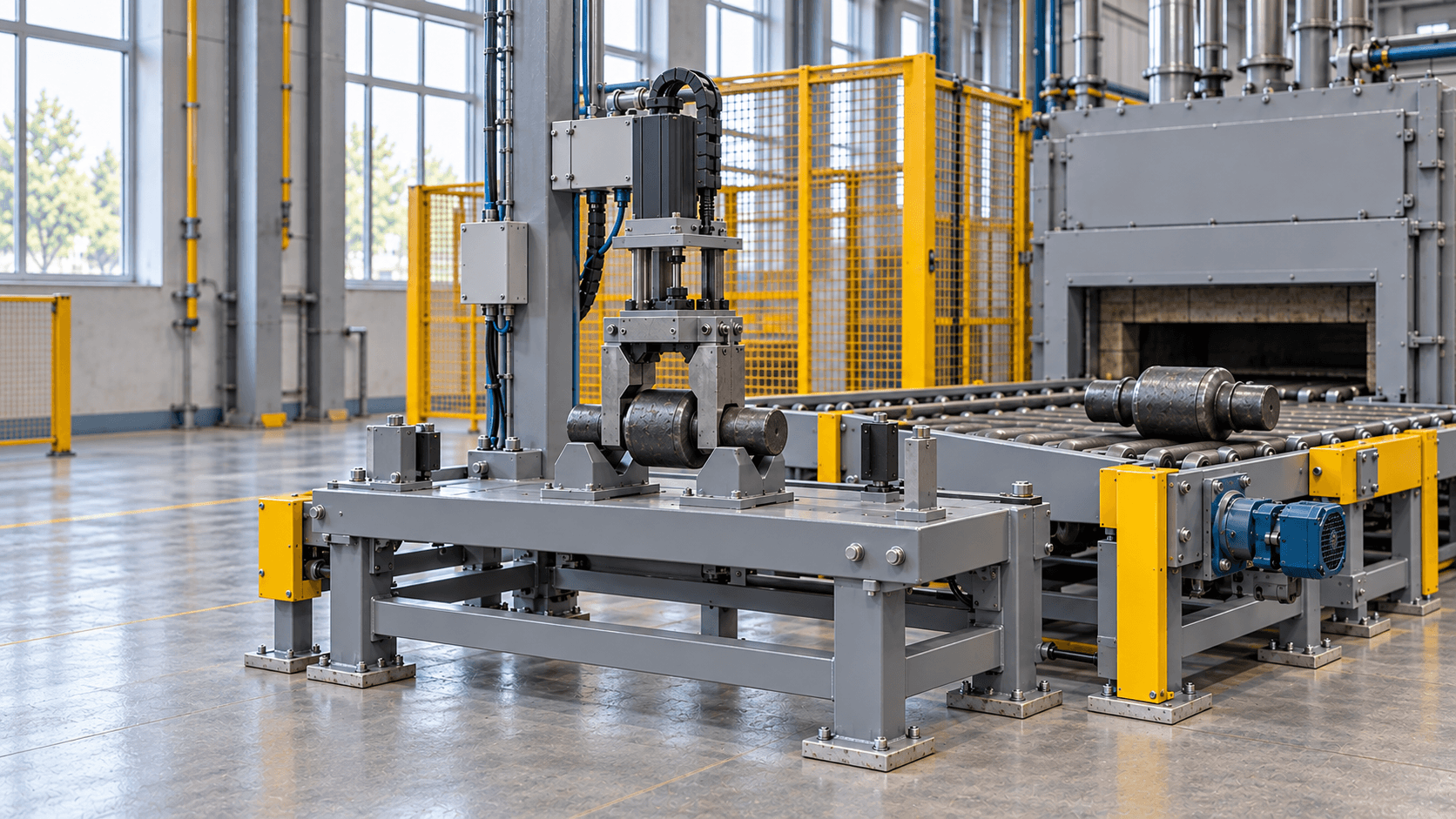
Check trimming, temperature measurement, gripping, waiting and quench-entry sequence. Record temperature distribution and rhythm variation.
Segregate and review abnormal incoming parts. Exceeding the permitted temperature or microstructure window does not mean a part can simply be reheated and released.
Point to equipment or select a step to see its location and action
Scroll horizontally for the complete line, or select a step below
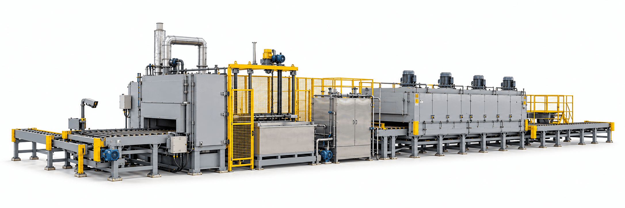
Match quench medium and cooling conditions to material, effective section and target microstructure.
Equipment: Transfer / quench
Decide whether incoming parts can be released before selecting the route. Forging and trimming are upstream interfaces whose supply scope must be listed separately.
Define finishing and trimming order and finishing-to-quench timing events against the adopted process. Supplemental heating is allowed only within a validated process window. Cleaning and draining depend on the medium and downstream requirements.
Validate surface measurements against representative sections. Tempering remains a separate operation. Equipment illustrations show functional relationships; internal transfer, dimensions and foundations require technical design.
Highlights identify functional areas. Equipment and layout follow the agreed proposal.
When release conditions are not met, segregate and review using this route.
Re-release requires an applicable process basis. Longer equalization or simple reheating must not be assumed to restore a lost direct-quenching window.
Resolve incoming-part release, rapid transfer, quench cooling and tempering handover before sizing each section.
Scroll horizontally to view the complete comparison
| Configuration item | Equipment & interface requirements |
|---|---|
| Entry temperature checks & diversion | Define measurement positions, field of view, emissivity checks and part identification. Route abnormal parts to a segregation station and retain records. |
| Holding, equalization or supplemental heating | Provide these only when needed and permitted by the microstructure window. Furnace setpoint cannot substitute for actual part-temperature verification. |
| Transfer & quenching | Size transfer, medium circulation and heat exchange against gripping, timing events, quench-entry orientation and maximum instantaneous heat load. |
| Cleaning & separate tempering | Check medium residue, allowable post-quench waiting, loading and tempering soak. Match buffer capacity to forging output rhythm. |
| Control & energy records | Link part or batch identity with temperature and process records. Define metering boundaries for forging heat, supplemental heating, quench circulation, tempering and utilities. |
Select quench medium and cooling intensity against material, effective section and target microstructure, not an equipment photograph.
Capacity is jointly limited by forging output, temperature sorting, transfer, instantaneous quench heat load, cleaning and tempering. Compare energy on equivalent products and quality criteria, stating the baseline route, conforming output and metering boundaries. Do not assume a fixed saving percentage.

Define equipment and auxiliary responsibilities from the post-forging handover to the agreed tempering discharge point.
The illustration does not cover an entire forging shop. Forging equipment, civil works and utilities are included only where specified in the technical agreement.
Agree equipment functions, process performance and product verification separately.
Verify temperature measurement and identification, abnormal-part diversion, gripping and transfer, circulating cooling, stop/restart functions, alarms and interlocks.
Record finishing-to-quench timing, thermal condition, medium temperature and tempering curves for representative operation. Verify temperature measurement as agreed.
Agree hardness, microstructure, mechanical properties, decarburization, crack and dimensional checks, including sample locations, against the adopted product specification.
Compare energy per conforming product, stating the baseline route, product mix, start/stop conditions and metering points.
Define conditions and responsibilities separately for equipment acceptance and product inspection. Agree representative materials, loading, sampling and pass criteria.
Review selection, auxiliary equipment and site integration for this process.
No. This route retains high-temperature tempering. Holding, equalization or supplemental heating may also be required within the permitted microstructure and temperature window. First validate the material and actual finishing condition.
Define measurement positions, surface condition, emissivity, field of view and part orientation, and establish a verification method. Infrared measurement describes the observed surface; it is not direct evidence of core temperature or acceptable microstructure.
Identify and segregate out-of-window, cold or uncertain parts, then decide disposition from material and process records. Include short-stop buffering, long-stop diversion, a conventional reheating route and restart first-off checks in the proposal. Do not simply reheat and release every stopped-line part.
Compare energy per conforming product on the agreed baseline and residual-heat routes. Record output, quality, start/stop conditions and electricity, gas and utility boundaries. Removing one heating stage does not establish whole-line savings.
Not by default. Agree microstructure, mechanical properties, decarburization, cracks, dimensions and sampling locations against material, use and the product specification. Equipment-function acceptance does not replace product verification.
Forging Residual-Heat Quench & Temper Line · Project consultation
Tell us about the workpiece, throughput or existing equipment issue. Drawings and detailed parameters can follow.
What you will receive