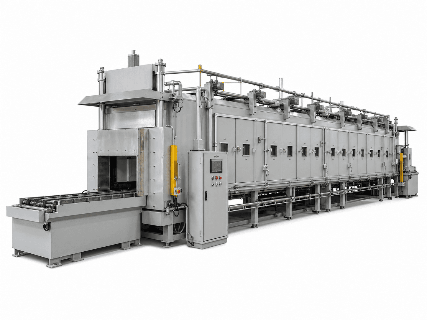
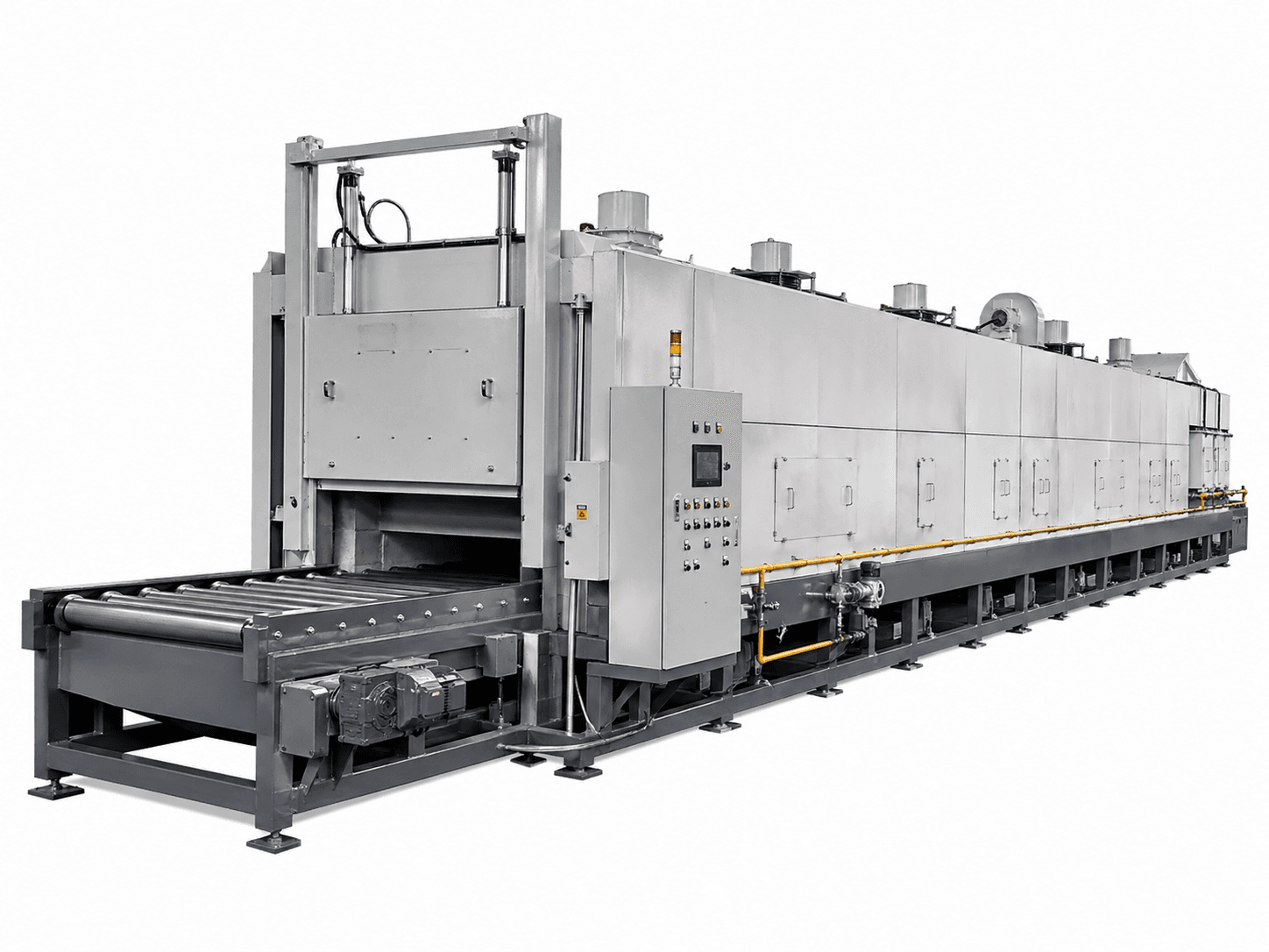
Billets and bars supported across beams
Confirm length, section, weight, contact locations and acceptable support marks before setting beam spacing.

WALKING BEAM FURNACE
For loads that rest stably on beams and have a relatively consistent production rhythm. Match support spacing, pitch and handling to the heating zones, residence time and step cycle.
Configuration and acceptance conditions are agreed for each project.
Match the workpiece, loading method and production rhythm before choosing the furnace arrangement.
Confirm length, section, weight, contact locations and acceptable support marks before setting beam spacing.
Assess loading, indexed movement and heating together as a continuous production system.
Compare other support and transport arrangements where loads are unstable, prone to jamming or change substantially.
First confirm stable support on the fixed and moving beams and compatibility with loading and discharge. Small loose parts, unstable loads or frequent major changes may require a different support or transport arrangement.
These are design inputs. Select and verify the final arrangement against the actual process.
Mechanical step rate is only one input. Conforming output also depends on material, section, spacing, heating time and changeovers.
Load positions and residence time in each zone determine heating conditions; overall length alone is insufficient.
Assess beam contact, hot deflection and surface requirements together; beam transport is not contact-free treatment.
Specify downstream cooling, handling and utilities separately. Water-cooled components require agreed water conditions and protection.
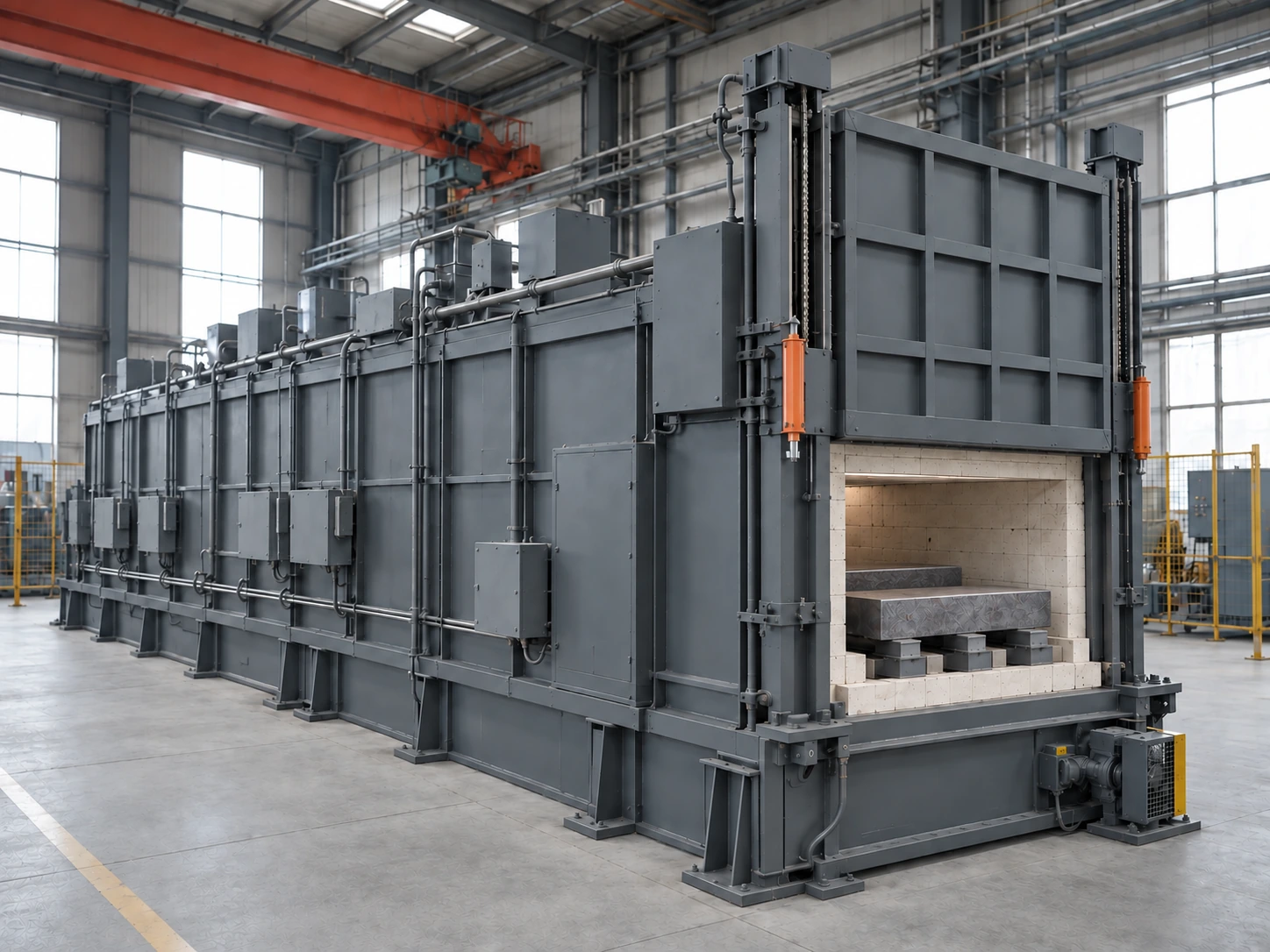
This illustration shows a walking-beam arrangement. Supports, pitch, heating zones and discharge cadence depend on the load; beam transport differs from pushing or roller conveying.
Check handling interfaces, drives, maintenance access, foundations and utilities. Beam support and cooling depend on temperature and load; water-cooled components require separately agreed water conditions, monitoring and protection.
Use the illustration to discuss equipment interfaces. Final details follow the agreed design.
Provide length, section, piece weight and permitted contact points.
Check stable support, hot deformation and clearance against jamming.
Coordinate indexed movement with the heating cycle and production rhythm.
Confirm heat source, heating/holding conditions and workpiece temperature requirements.
Check handling interfaces, drive space, foundations and maintenance routes.
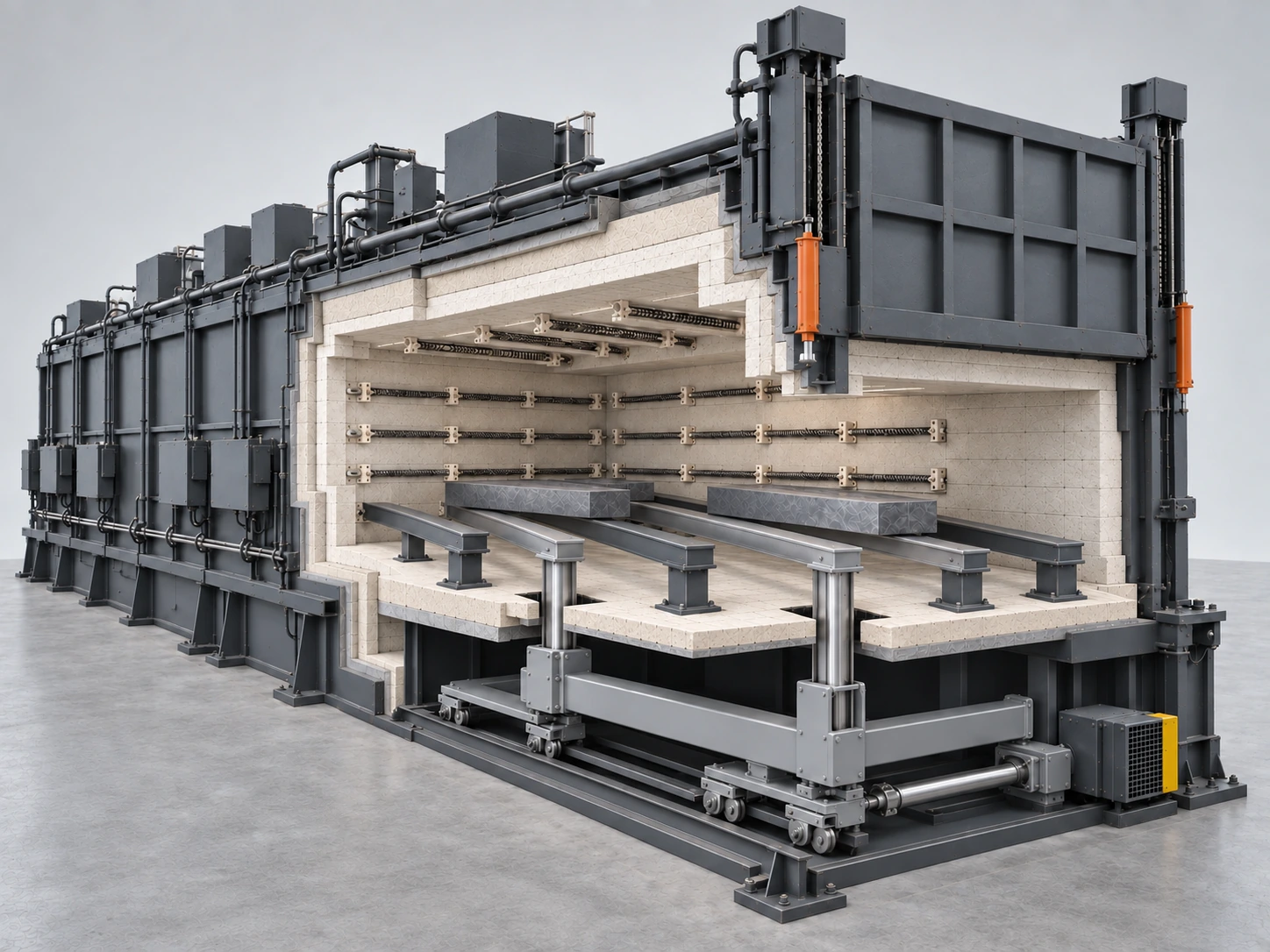
Walls, roof and hearth enclose the heated space; the section reveals the insulation layers.
Electric heating is illustrated; the heat source and zone arrangement follow the actual process.
The dark supports are fixed beams that receive the load as the moving beams lower; spacing follows workpiece geometry.
The light supports are moving beams driven from below to lift, advance, lower and return, alternating support with the fixed beams.
Loads must rest stably across the beams; agree contact points and permissible support marks.
Moving beams connect through hearth slots to the carriage. Lift mechanisms and roller guides provide vertical and longitudinal movement, with clearance from the fixed hearth.
Moving beams lift, advance, lower and return. The workpieces advance with the beams, then rest on the fixed beams while the moving beams return underneath.
Loads enter, pass through and leave in sequence. Production is continuous, while individual movements include dwell and indexed steps.
Walking beams alternately lift and move the load; pushers advance it by pushing, and roller hearths use rollers. Select according to support, surface requirements, geometry and cadence.
Heating and quality requirements still apply. A shorter step cycle changes residence time, so mechanical speed alone cannot establish conforming output.
Check handling layout, drive and maintenance access, foundations, utilities and load handling after an abnormal stop. Assess water cooling only where included in the design.