
Plate, strip, bars and tubes
Regular parts continuously supported by multiple rollers and travelling stably through the zones.

Loading page…
Loading is taking longer than usual. Please wait or try again.
Retry loading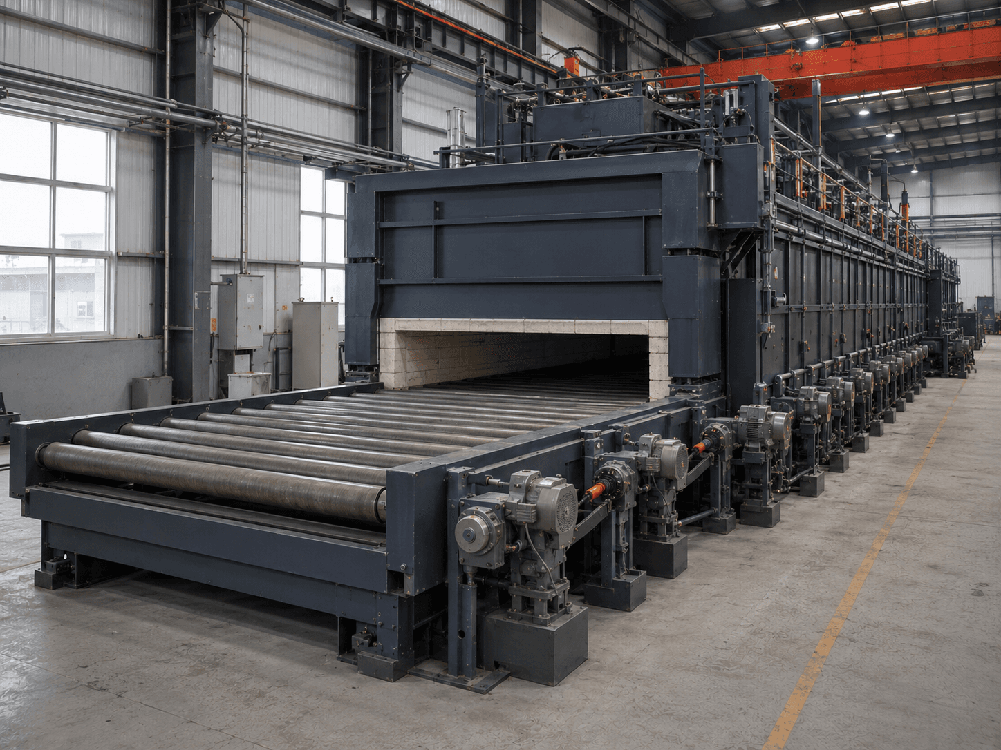
ROLLER HEARTH HEAT TREATMENT FURNACE
For plate, strip, bar, tube and regular parts stably supported on rollers. Assess support span, line load, roller pitch, speed and process time before defining effective width, temperature zones and cooling interfaces.
These existing Suneng project data are selection references only. The recorded 5–20 m/min speed needs clarification as entry/exit, reciprocating or steady process speed; do not calculate heating time or capacity directly from it. Verify supports, roller loads and process cycle for each project.
Assess workpiece shape and loading or conveying first to determine suitability for a roller-hearth furnace design.
Regular parts continuously supported by multiple rollers and travelling stably through the zones.
Check number of supports, minimum length, overhang, line load and hot distortion.
Compare belt, pusher or batch furnaces.
The same total weight creates different roller loads at different part lengths and support spans. Maximum unit weight cannot replace a roller-system check.
These are configuration options to confirm against operating conditions.
Zoned resistance heating
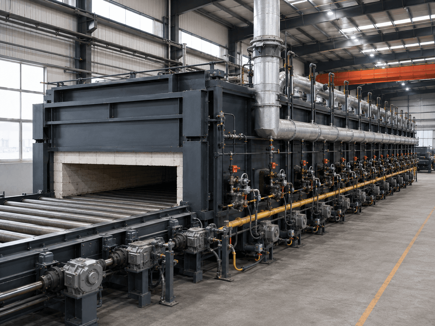
Combustion, furnace pressure and flue exhaust
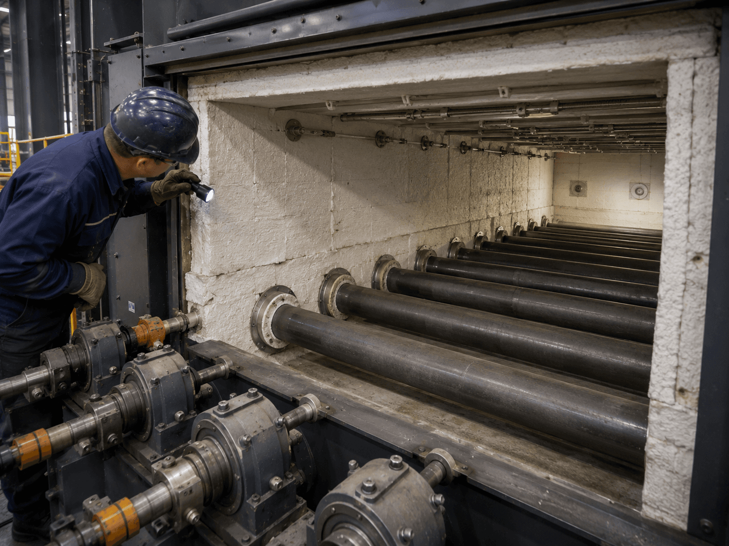
Continuous openings and atmosphere zones
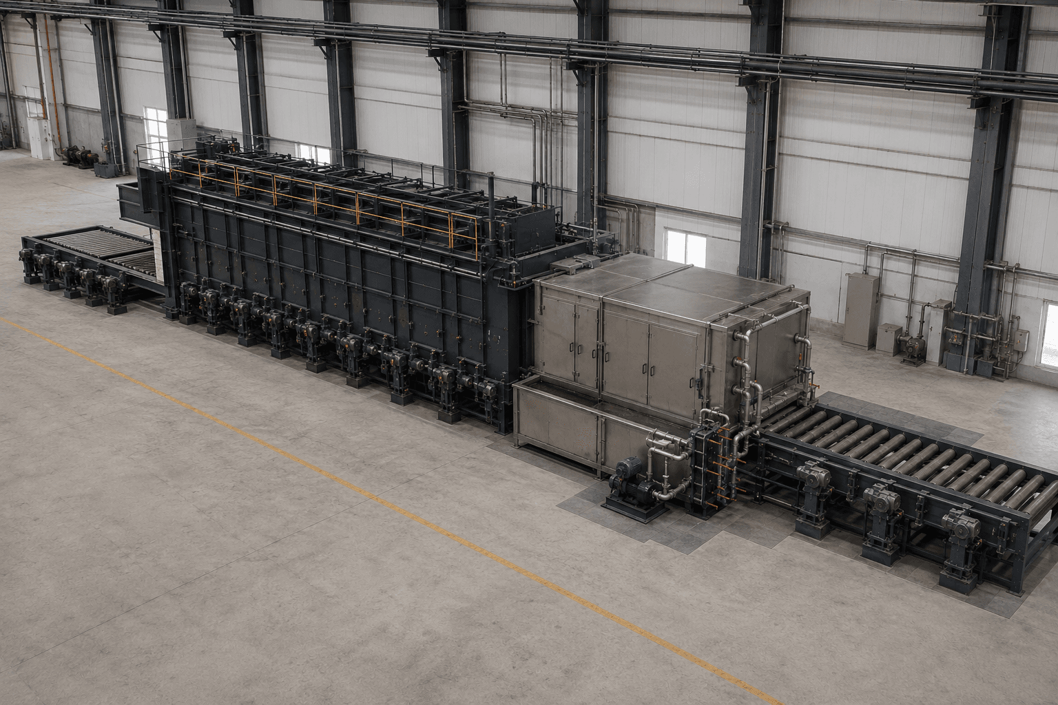
Heating, transfer and cooling
| Configuration | Better-suited conditions | Main advantage | Required checks | Do not promise without verification |
|---|---|---|---|---|
| Electrically heated roller-hearth furnace | Continuous annealing, tempering and heating of regular parts | Arrange temperature zones around the effective zone and conveying speed | Effective width, roller pitch, line load, speed and zones | Do not promise output or uniformity without defined supports and loading |
| Gas-fired roller-hearth furnace | Continuous heating with defined site gas and exhaust conditions | Compare designs using furnace scale and available energy | Burners, furnace pressure, exhaust, roller seals and safety interlocks | Burner specifications do not replace whole-furnace performance acceptance |
| Protective-atmosphere roller-hearth furnace | Long parts requiring oxidation, decarburization or surface control | Organize a continuous atmosphere system around zones and openings | Openings, roller seals, atmosphere, discharge, monitoring and interlocks | Gas flow rate alone does not establish surface quality |
| Roller-hearth furnace with rapid-cooling section | Regular parts needing controlled cooling after normalizing or rapid cooling after solution treatment | Continuous rollers provide a defined transfer route | Exit temperature, cooling intensity, straightness, conveying and interlocks | Do not guarantee microstructure, properties or flatness without adequate trials |
Separate working space, loading/conveying variables and structural variables to create a verifiable design.
| Data group | Items to confirm |
|---|---|
| Workpiece | Material, width/thickness/length or diameter/length, mass, straightness and surface |
| Supports | Direct roller or tray support, minimum length, support span and line load |
| Process | Continuous/maximum temperatures, effective time, atmosphere and curves |
| Conveying | Speed, alignment, entry/exit, spacing and specification changes |
| Cooling | Air, forced-air, quench or post-solution rapid cooling and transfer boundaries |
| Utilities | Power or gas, exhaust, atmosphere, cooling and full-line space |
Structure examples explain components. Final layout depends on workpieces, process, load, cycle and site conditions.
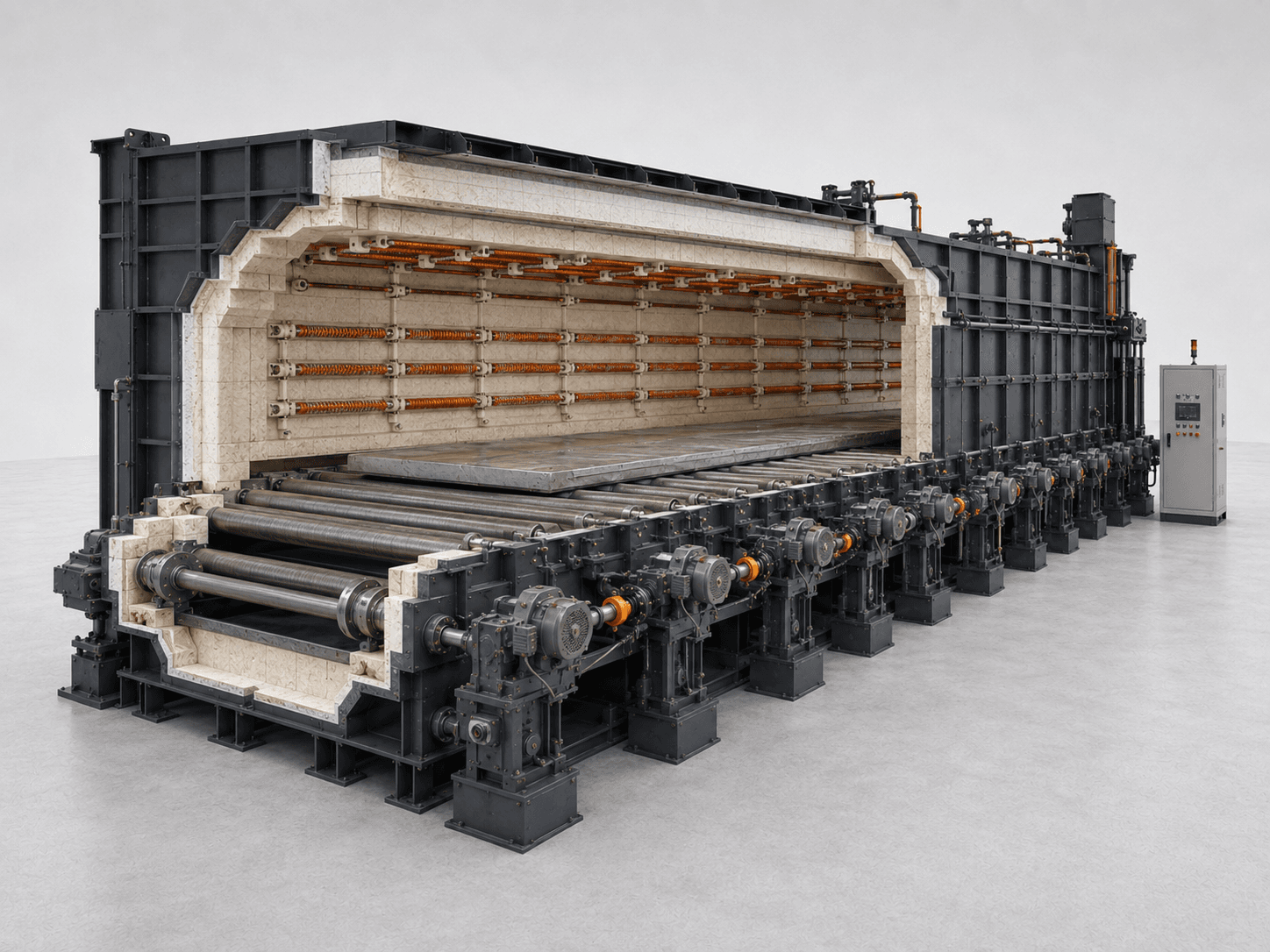
Confirm minimum length, overhang and alignment together.
Define separately from roller-face length and chamber structure.
Calculate from actual supports and dynamic conditions.
Determine from hot strength, speed and maintenance requirements.
Define the continuous process and production cycle.
Divide sections by process, thermal load, heat source and maintenance.
Configure resistance or gas systems for effective time and zone curves.
Check rollers, bearings, seals, cooling and replacement method against hot loads.
Coordinate sectional drives, speed synchronization, alignment, tracking and blockage protection.
Confirm openings, roller seals, purging, discharge and cooling interfaces together.
Agree on temperature control, records, speed coordination, alarms and full-line emergency stops.
These answers explain selection boundaries, not the final technical design or contract annexes.
Plate, strip, bars, tubes and regular long parts stably supported by rollers are candidates. Check minimum length, support span, line load, straightness and process time.
Compare roller hearths when parts or trays can travel stably directly on rollers. Assess pushers when standard trays must advance at a fixed pitch and maintain a specific orientation.
Part length, support count, span, centre of gravity and conveying impacts change the force on each roller. Calculate for the most adverse position.
Use effective heated length, heating/soaking time, zone curves, cooling and adjacent cycle rates. Target output alone is insufficient.
Provide material, maximum/minimum sizes, unit mass, support method, line load, continuous/maximum temperatures, process time, speed, atmosphere, cooling and adjacent interfaces.
Compare loading or conveying arrangements first, then discuss the complete operating conditions.
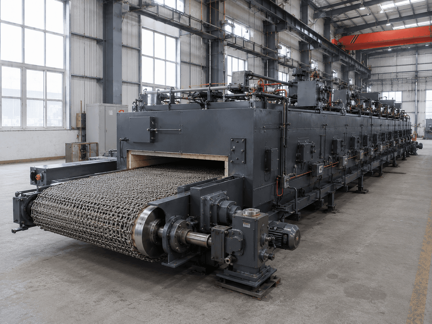
Compare mesh belts for flat or bulk small-part loading.
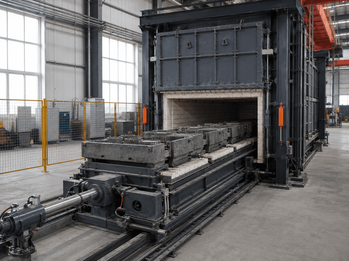
Compare pushers for parts requiring tray positioning.
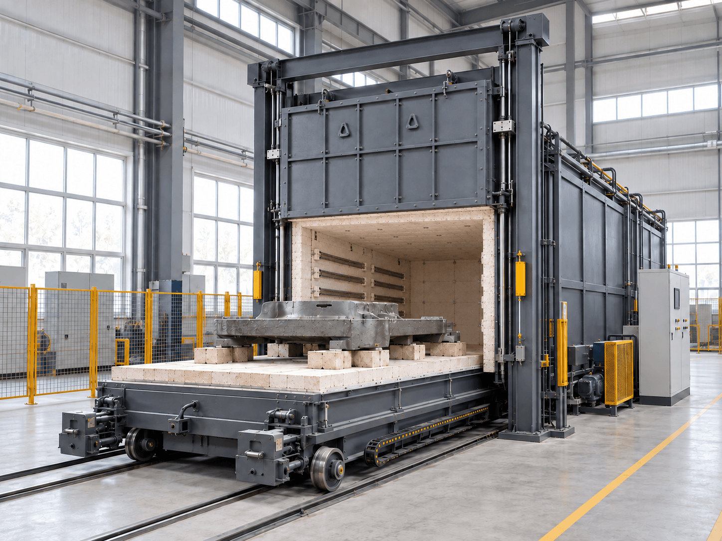
Compare batch loading for varied large heavy parts.
Tell us about the workpiece, throughput or existing equipment issue. Drawings and detailed parameters can follow.
Prefer to talk first? Contact us directly.
What you will receive