
Fasteners, hardware and small mechanical parts
Batch parts that can lie flat or form controlled layers and travel continuously through the temperature zones.

Loading page…
Loading is taking longer than usual. Please wait or try again.
Retry loading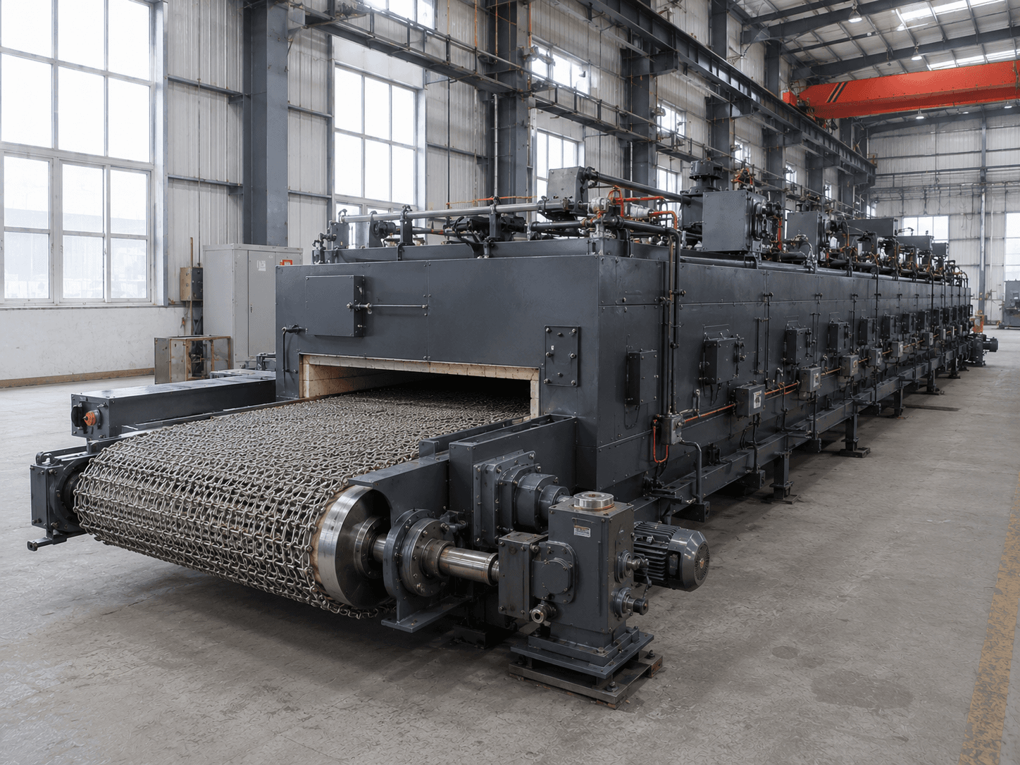
MESH BELT RESISTANCE HEATING UNIT
For small parts spread flat or in controlled layers on a belt. Assess part shape, loading pattern, belt material, process time and adjacent cycle rates before defining effective conveying width, heated length and cooling route.
150–1,200°C is the scope of GB/T 10067.41-2013, not a continuous working-temperature guarantee for all Suneng belt furnaces. Confirm temperature against belt material, atmosphere, load and service life. Dimensions are project examples; check capacity against loading and process time.
Assess workpiece shape and loading or conveying first to determine suitability for a mesh belt furnace design.
Batch parts that can lie flat or form controlled layers and travel continuously through the temperature zones.
Use loading trials to check rolling, overlap, shielding and load per unit area.
Compare pusher, roller-hearth, box or bogie-hearth furnaces.
Belt width and speed alone do not establish capacity. Also consider loading density, effective heating time, thermal load, adjacent bottlenecks and target yield.
These are configuration options to confirm against operating conditions.
Continuous heating and soaking
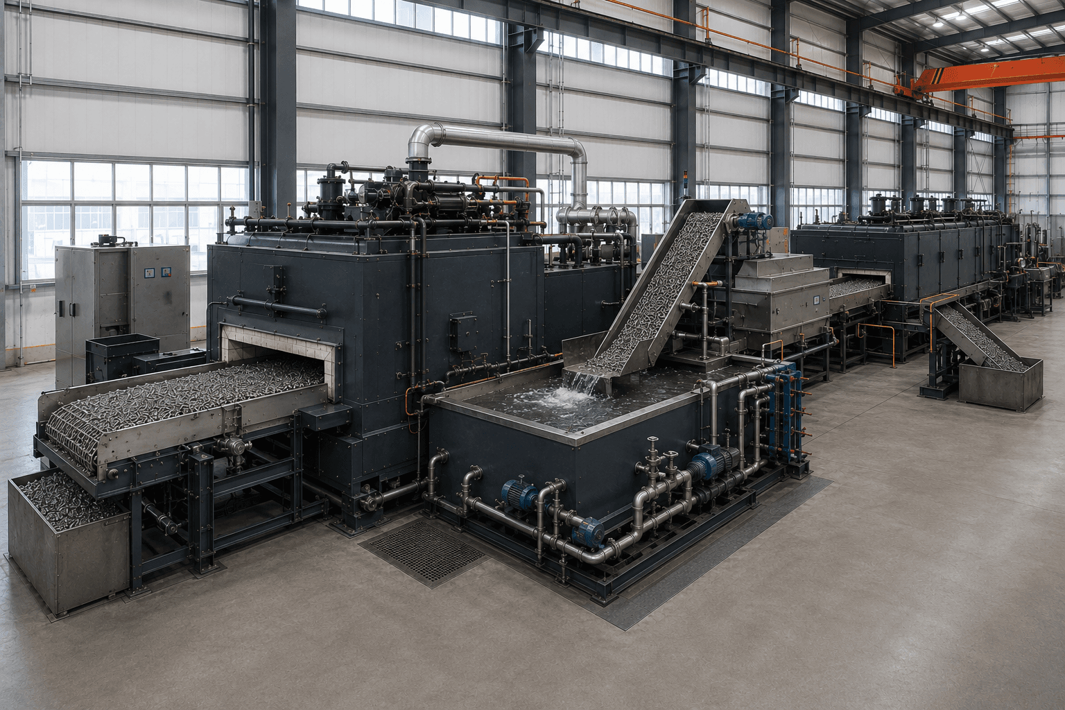
Heating, transfer and cooling
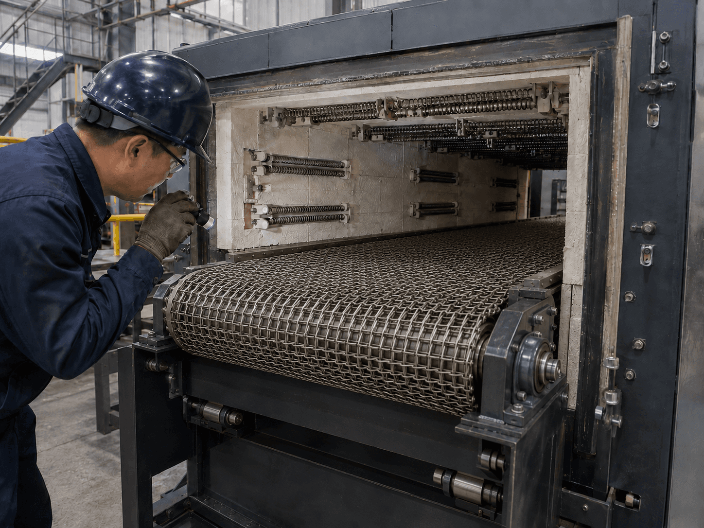
Sealing, purging and continuous conveying
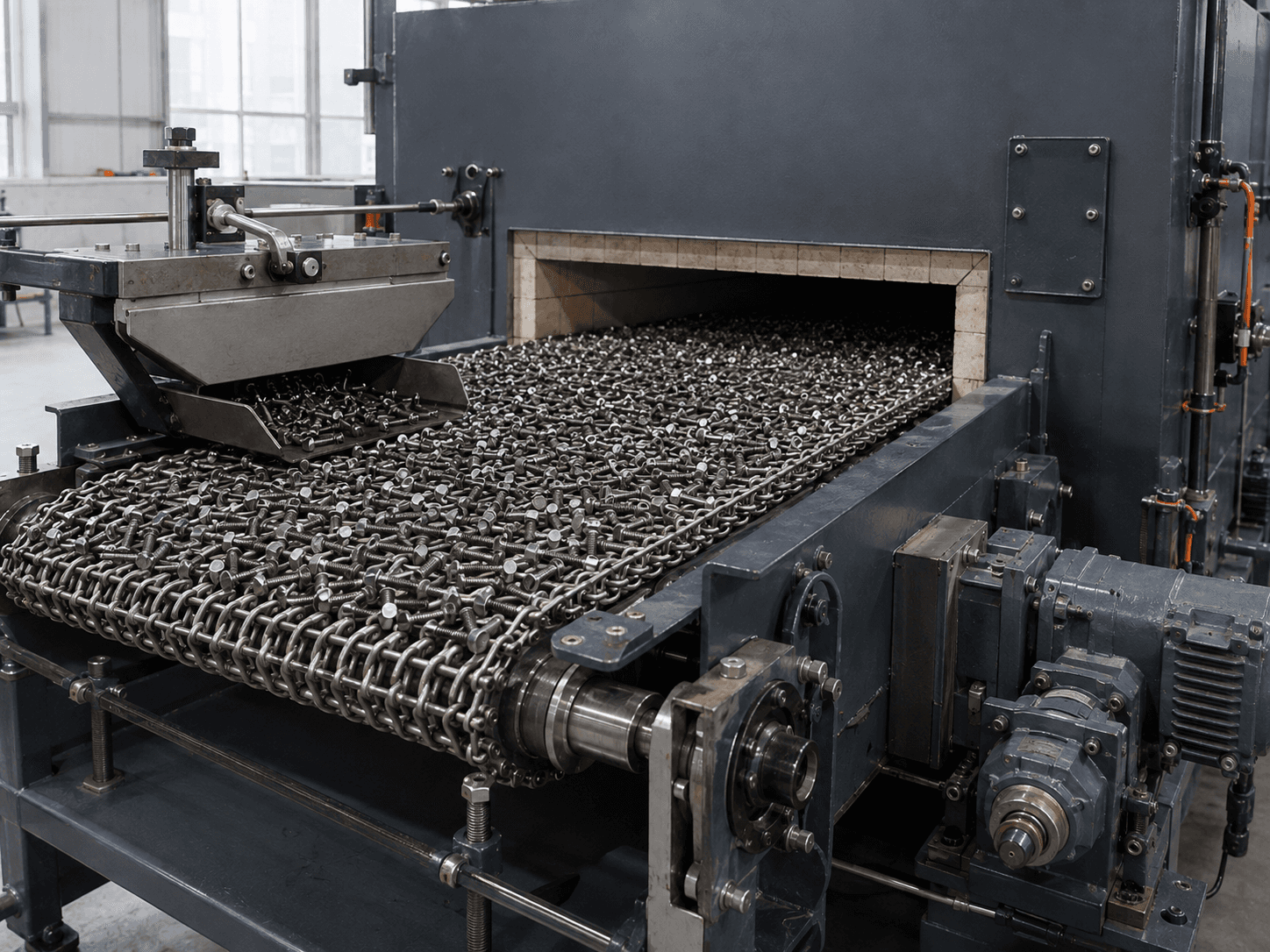
Standalone continuous treatment
| Configuration | Better-suited conditions | Main advantage | Required checks | Do not promise without verification |
|---|---|---|---|---|
| Continuous annealing / tempering mesh-belt furnace | Assess annealing, tempering and stress relief of stable small-part batches | Continuous loading/discharge supports integration with adjacent equipment | Loading, effective width, speed, zones and belt material | Do not promise output or uniformity without actual loading conditions |
| Mesh-belt quench-and-temper unit | Small parts with stable routes requiring continuous quenching and tempering | Design multiple operations around a common production cycle | Transfer, medium, washing, tempering, cooling and interlocks | Do not guarantee microstructure or distortion without adequate process trials |
| Protective-atmosphere mesh-belt furnace | Continuous duties requiring control of oxidation, decarburization or surface condition | Establish atmosphere zones and interfaces around continuous conveying | Gas composition, opening seals, purging, discharge and interlocks | Gas flow rate alone does not establish surface quality |
| Compact mesh-belt furnace | Small-part duties with simple interfaces and few process sections | Concentrated equipment scope facilitates connection to existing handling | Feeding, collection, speed, effective time and service space | Do not promise full-line efficiency before adjacent operations are defined |
Separate working space, loading/conveying variables and structural variables to create a verifiable design.
| Data group | Items to confirm |
|---|---|
| Workpiece | Material, dimensions, unit mass, shape and surface condition |
| Belt loading | Single/multiple layers, mass per unit area, feed rate and jamming tendency |
| Process | Continuous/maximum temperatures, effective time, atmosphere and curves |
| Cooling | Air, forced-air or liquid cooling, transfer and washing requirements |
| Production | Target cycle, shifts, changeovers, adjacent interfaces and target yield |
| Utilities | Power or gas, atmosphere media, exhaust, cooling and installation space |
Structure examples explain components. Final layout depends on workpieces, process, load, cycle and site conditions.
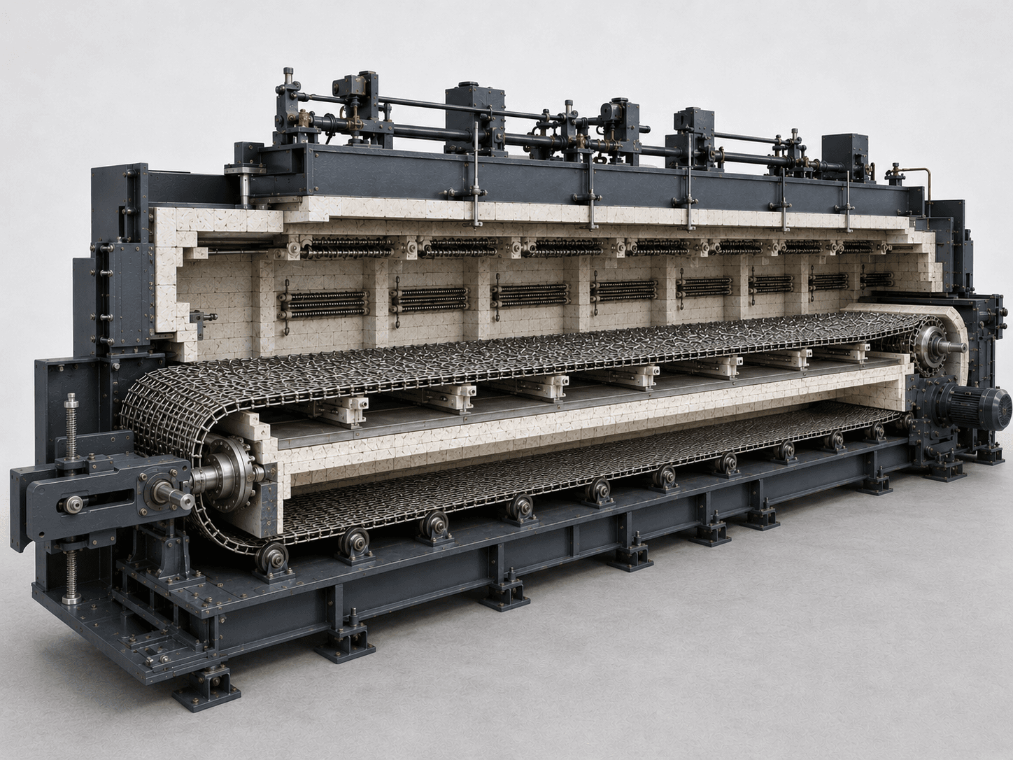
Check single-layer or stacked loading, rolling, jamming and shielding risks.
Define separately from total belt width and structural opening dimensions.
Used for belt, support, thermal-load and capacity calculations.
All three must correspond in the process and zone layout.
Define continuous-operation and maintenance boundaries.
Divide sections by temperature zones, heat loss, atmosphere and maintenance.
Configure zones around thermal load, process curve and continuous conveying.
Check belt, sprockets, support rolls, guides and return path for temperature and load.
Check motor, reduction drive, tensioning and tracking adjustments for speed and load.
Confirm opening seals, purging, discharge, cooling and adjacent interfaces as a system.
Confirm discharge sprockets, guides, return and adjacent connections against the full-line cycle.
These answers explain selection boundaries, not the final technical design or contract annexes.
Fasteners, hardware and small mechanical parts that remain stable in flat or controlled-layer loading, do not snag or roll off and suit continuous feeding are candidates.
No. Loading density, load per area, effective heating time, thermal load, cooling and adjacent cycle rates also constrain output. Calculate using actual loading and process data.
Higher speed reduces heating and soaking time and may affect temperature, microstructure and surface. Determine speed together with effective length, zones and process time.
Continuous feeding complicates opening seals, purging, belt return, discharge and safety interlocks. Design and accept atmosphere and conveying systems together.
Provide material, dimensions, unit mass, loading pattern, feed rate, continuous/maximum temperatures, process time, atmosphere, cooling route and adjacent interfaces.
Compare loading or conveying arrangements first, then discuss the complete operating conditions.
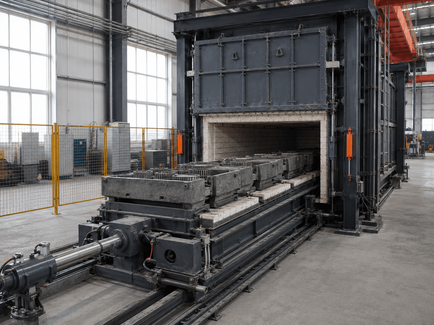
Compare tray conveying for parts unsuitable for direct belt loading.
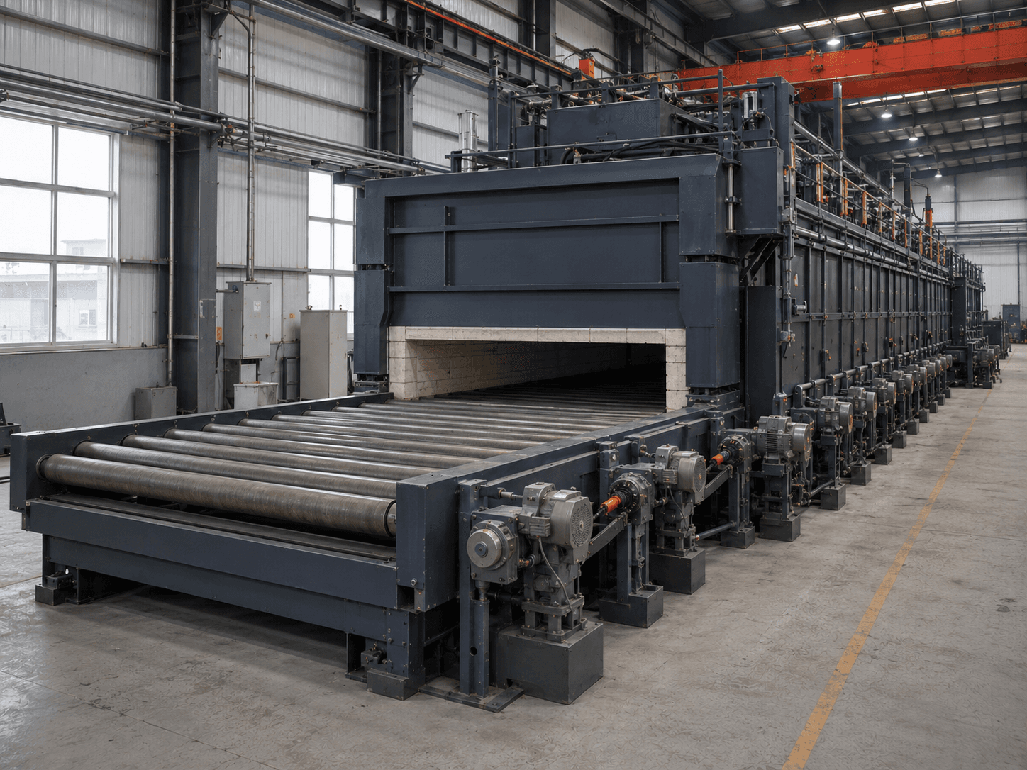
Compare rollers for plate, strip and regular long parts.
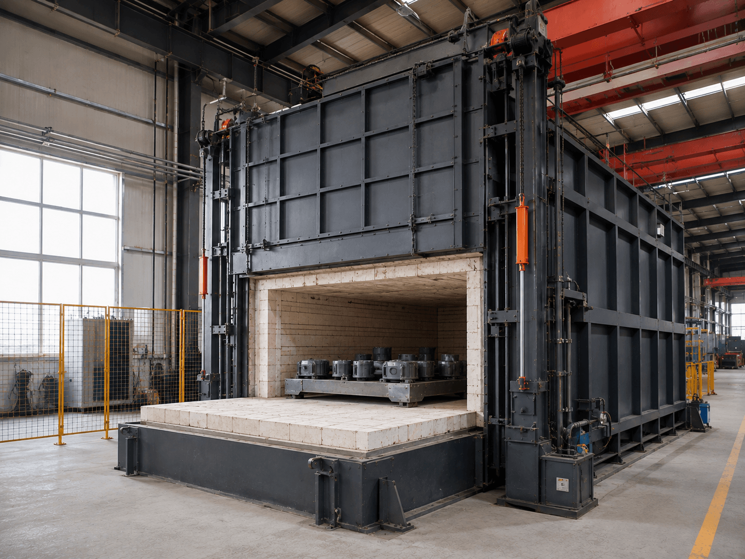
Compare batch loading for varied small-batch work.
Tell us about the workpiece, throughput or existing equipment issue. Drawings and detailed parameters can follow.
Prefer to talk first? Contact us directly.
What you will receive