Castings and forgings with stable support
The forks need room to enter and lift. Check support, centre of gravity and contact points in the hot condition.

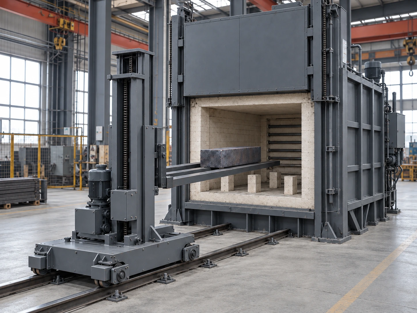
FORK-HANDLING FURNACE
For castings, forgings and batch loads that can be supported by forks. Confirm clearance beneath the load, centre of gravity and the unloading route before coordinating the chamber, handler and downstream stations.
Configuration and acceptance conditions are agreed for each project.
Match the workpiece, loading method and production rhythm before choosing the furnace arrangement.
The forks need room to enter and lift. Check support, centre of gravity and contact points in the hot condition.
Evaluate door opening, fork pickup and downstream cooling as a coordinated process route.
Assess fixtures and support first. Compare other loading or transport methods when the load cannot be picked up stably.
Check stable support under the workpiece, its centre of gravity and clearance for the forks. Time-sensitive processes also require coordinated unloading, pickup and transfer to downstream equipment.
These are design inputs. Select and verify the final arrangement against the actual process.
Parts, fixtures and required clearances determine the working space; part dimensions alone are insufficient.
Check the combined load condition of forks, fixtures and parts; lifting capacity alone does not establish stability.
Define start and end events across unloading, pickup, travel and downstream entry. Travel speed is not process transfer time.
Specify the medium, cooling equipment and part inspection separately; fork handling does not imply a complete quench system.
The forks handle loads; this is not a fin-skiving machine. Quench equipment, medium and permitted transfer time must be specified for the material and process.
Provide the travel area, foundations, maintenance access, lifting route and utilities. List responsibility for the furnace, handler, quench equipment and installation separately before comparing prices.
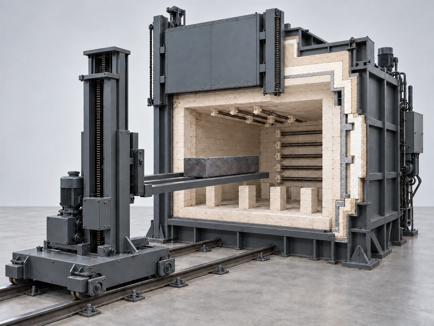
Use the illustration to discuss equipment interfaces. Final details follow the agreed design.
Provide dimensions, weight, centre of gravity and hot support points.
Confirm underside clearance, support spacing and pickup contact points.
Check clear opening, lift height and rail travel.
Material, temperature and cycle define heating and lining requirements.
Define transfer start/end events and list cooling or quench equipment separately.
The section shows shell, insulation and hot face; materials and thickness follow the process.
The illustration shows electric heating; elements and ceramic holders depend on temperature, loading and maintenance.
Coordinate the clear opening, door travel, insulation and sealing with the handling motion.
Supports carry the hot load while preserving fork access between support points.
Check pickup against underside clearance, centre of gravity, fork spacing and hot deformation.
The separate handler provides lift and travel; rail alignment and door interlocks are project-specific.
The workpiece rests on furnace supports during heating. With the door open and clearance verified, forks enter below the load, lift it, withdraw and transfer it as required by the process.
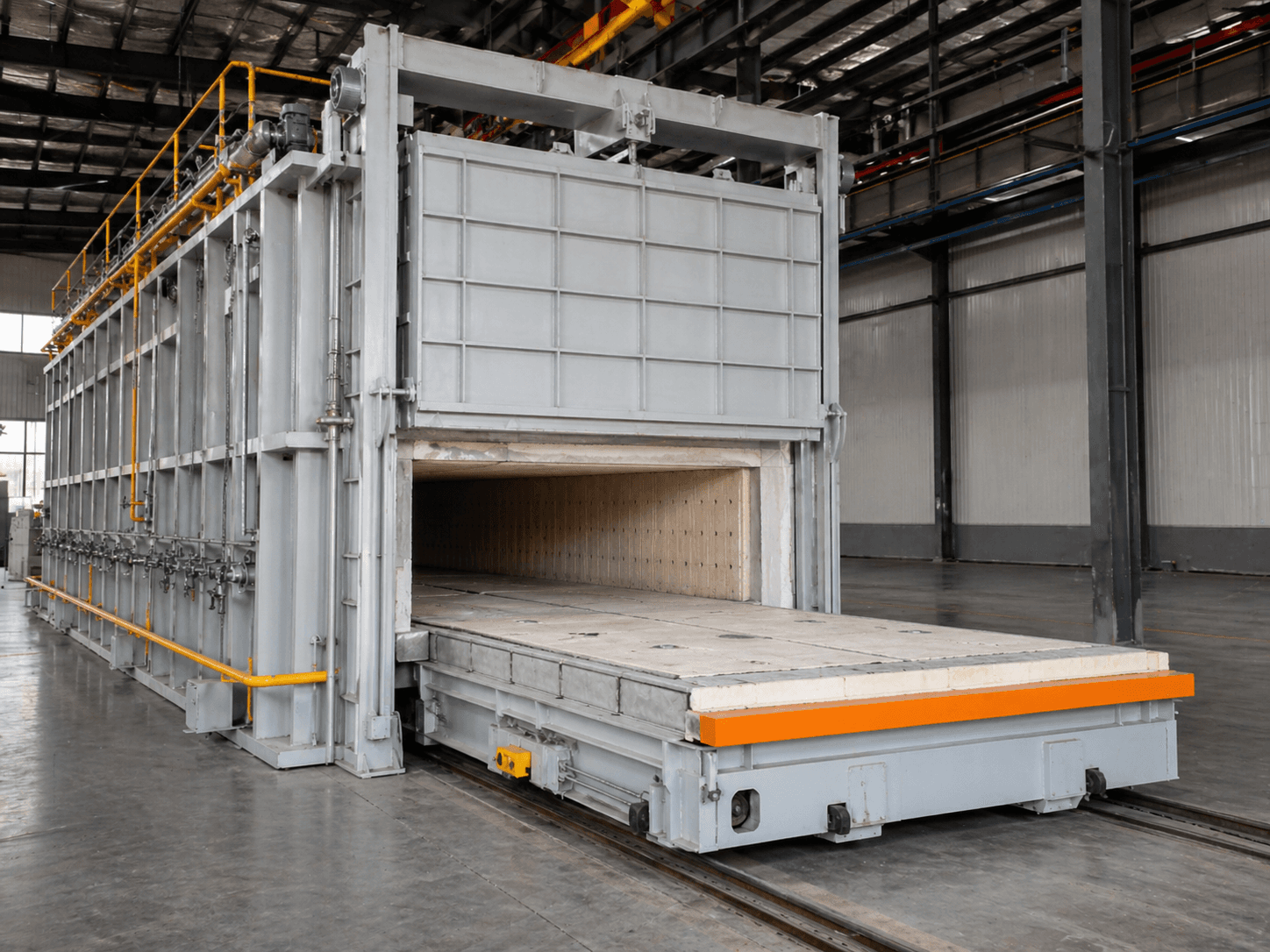
Here, a separate handler lifts the load into and out of a fixed chamber. A trolley furnace carries the load on its moving hearth. Compare support, loading routes and transfer requirements.
That depends on the material and process. Specify the chamber, handler and cooling or quench equipment separately.
Dimensions, centre of gravity, supports, underside access and fixtures are also required. Equal-weight parts can need different handling arrangements.
Provide a drawing or dimensions and weight, material and cycle, support and fork access, transfer requirements and the rail and downstream layout.