

Start with belt speed × actual usable loading width × workpiece mass per unit belt area × 60. With speed in metres per minute, width in metres and loading in kilograms per square metre, the result is kilograms per hour. The permissible speed must also satisfy the minimum time required in each critical process zone, including carburizing and diffusion: use the most restrictive limit. Then check that heating, atmosphere supply, quenching, washing, tempering and material handling can sustain the same flow.
Geometric throughput is not qualified production output. A kilograms-per-hour figure alone does not establish compliance with the required workpiece properties. Jiangsu Suneng Industrial Furnace Co., Ltd. recommends calculating throughput against the workpiece, zone times and loading arrangement together. Carburizing introduces carbon into the steel surface; subsequent treatments, including quenching, develop the required hardened case.
Combine two constraints
The first is process time. Under the confirmed temperature, atmosphere and loading conditions, the workpiece must remain in each relevant zone long enough. Increasing belt speed reduces residence time in a fixed length.
The second is loading capability. Mass flow depends on speed, actual usable loading width and workpiece mass per unit belt area. The last quantity means the mass laid on each square metre at the specified spacing, orientation and number of layers. It is not steel density.
Apply these constraints together. If process time is insufficient, limit speed first. If time is adequate but loading restricts flow, assess the arrangement, effective width or equipment configuration. Multiplying maximum mechanical speed by maximum loading does not establish carburizing capacity.
What time does furnace length divided by speed actually give?
Ask the supplier to distinguish the following lengths on the zone drawing.
| Term | Meaning for the buyer | Can it directly establish effective carburizing length? |
|---|---|---|
| Overall furnace length | External or structural length from entrance to exit, potentially including transition sections; the complete line contains other equipment | No |
| Effective heating zone | Working region defined in the technical documents for heating the workpieces | Not automatically in full: workpieces may still be heating up |
| Carburizing zone | Process section assigned to supplying carbon to the workpiece surface | Only after verifying actual workpiece temperature, atmosphere and zone boundaries |
| Diffusion zone | Where separately provided, a stage mainly for redistributing carbon inward and adjusting surface carbon | Check its temperature, carbon potential and time separately; do not reassign its length to the preceding stage |
Carburizing and diffusion describe process functions. They do not mean every furnace has two physically isolated chambers; inward diffusion also occurs during carburizing. Do not double-count overlapping sections. Case development depends on the workpiece's temperature, atmosphere and time history, not simply on the names attached to zones.
For a zone with confirmed boundaries and constant belt speed:
Zone residence time (min) ≈ effective zone length (m) ÷ belt speed (m/min).
This gives transit time. Cold workpieces also need to heat up. Time before reaching the specified temperature cannot simply be counted as equivalent time at the process temperature. Use workpiece temperature records or process validation for the relevant load to establish where effective time begins.
Once a zone's minimum required process time is established:
Speed limit imposed by that zone (m/min) ≈ effective zone length (m) ÷ minimum required time (min).
Check each stage separately. Sufficient total residence time does not prove that carburizing and diffusion each receive enough time.
Why can the target case depth limit belt speed?
Carbon first transfers from the furnace atmosphere to the steel surface and then diffuses inward. Effective case depth is measured from the surface to an agreed hardness threshold. It also depends on the subsequent hardening process and is not simply the distance carbon has penetrated. Specify the case-depth definition, measurement method, workpiece condition and acceptance threshold.
| Factor | Why it changes the time or throughput assessment | Buyer action |
|---|---|---|
| Material | Composition affects carbon diffusion and subsequent hardening response | Identify the steel grade and incoming condition; do not transfer times directly from another grade |
| Temperature | Within the applicable process range, higher temperature accelerates diffusion | Treat a temperature increase as a process change; reconfirm workpiece requirements and equipment suitability |
| Carbon potential | This control quantity describes the atmosphere's carburizing tendency, not gas flow rate; it affects surface supply and the carbon profile | Request stage settings and their basis; higher is not automatically better |
| Surface condition | Surface barriers can inhibit carbon transfer | Check cleanliness and pretreatment when incoming condition changes; do not rely only on longer time |
| Target effective case depth | A deeper target generally requires more time under comparable, diffusion-controlled conditions; final hardness also depends on material and quenching | Specify depth together with the hardness criterion and measurement position |
| Diffusion stage | Its time and carbon potential influence the final carbon distribution | Check carbon supply and subsequent diffusion separately, rather than preserving only total time |
The material and temperature relationships are discussed in the University of Cambridge Materials Algorithms Project carbon-diffusion documentation and the ASM Heat Treating Society carburizing-temperature resource. Carbon potential, surface barriers, stage allocation and case-depth distinctions are discussed on pages 9, 29–31 and 34 of Linde's Gas Carburising and Carbonitriding.
A diffusion model gives a reusable directional relationship: under idealized conditions with the same material, temperature, surface conditions, diffusion coefficient and initial, surface and target concentration boundaries, the characteristic depth at a specified carbon concentration is approximately proportional to the square root of time. This follows from a diffusion-equation solution. See the MIT steel-surface carburizing diffusion exercise.
Comparing multiples within this ideal model:
- Doubling the target characteristic depth requires approximately 2² = 4 times the cumulative effective diffusion time to reach the corresponding diffusion state. This does not mean the separate diffusion zone alone needs four times the time, or that every process stage automatically multiplies by four.
- The permissible belt speed falls to approximately one quarter only if effective process-zone conditions remain equivalent, effective process length is unchanged, zone proportions and process organization do not otherwise change, and this diffusion relationship still controls the principal time limitation.
- If actual usable loading width and workpiece mass per unit area also stay unchanged, geometric hourly throughput falls to approximately one quarter.
This ideal-model relationship explains why depth, time, speed and throughput do not scale by the same factor. It is not a universal formula for predicting actual effective hardened case depth, and cannot be applied directly across steel grades, temperature schedules, carbon-potential histories or quenching conditions. When a buyer doubles the target depth, it is unsafe to assume that time merely doubles: under ideal diffusion control, time demand can grow with the square of depth.
For the same workpiece, temperature schedule, carbon potential and loading, increasing speed below the confirmed minimum process time invalidates reliance on the previous case-depth commitment. Restore a speed that meets the requirement or reassess effective process length and the process plan.
How much can the belt actually carry?
Use consistent units in the area-based calculation:
Geometric mass throughput (kg/h) ≈ speed (m/min) × actual usable loading width (m) × workpiece mass per belt area (kg/m²) × 60.
The factor 60 converts minutes to hours. Omit it if speed is already in metres per hour. This is called geometric throughput because it describes mass transported with stable loading and continuous conveying, without establishing treatment quality.
Determine mass per unit belt area by laying out and weighing representative workpieces in the normal arrangement. Dimensions, piece mass, spacing and permitted overlap affect how much fits. Belt load capability at operating temperature, along with heat transfer, atmosphere exposure and heating capacity in layered loads, further limits whether that arrangement is usable.
A load that fits on a cold belt is not automatically suitable for continuous hot operation. Changing layer count or packing density may change the validated workpiece-heating and carburizing conditions. Increasing loading is not merely changing a multiplier.
Where one zone controls the line speed and all other conditions remain unchanged, its time-constrained geometric throughput limit is approximately: effective length ÷ minimum process time × effective loading width × workpiece mass per unit area × 60. This remains distinct from a guarantee of qualified line output.
Worked example: transport capacity is only the first check
Every numerical input below is an illustrative teaching assumption, not a Suneng equipment specification, customer condition, recommended carburizing schedule or production result. No actual steel grade or case-depth value is specified, and no process time is borrowed from literature as a recommendation.
Assumed inputs
Assume confirmed, non-overlapping carburizing and diffusion sections, adequate preceding heat-up, and a common constant belt speed. Required times are inputs to this example only.
| Item | Assumed value | Meaning in this example |
|---|---|---|
| Effective carburizing length | 6 m | Excludes the separately treated heat-up zone |
| Effective diffusion length | 2 m | Does not overlap the carburizing zone |
| Total effective process length | 8 m | Sum of these two sections only |
| Initial belt speed | 0.10 m/min | Constant continuous conveying |
| Actual usable loading width | 0.60 m | Width available for normal loading |
| Workpiece mass per unit belt area | 30 kg/m² | Assumed input, not proof that this arrangement is feasible |
| Minimum carburizing time | 75 min | Teaching input, not a recommendation for a steel grade |
| Minimum diffusion time | 40 min | Teaching input, not a recommendation for a case depth |
| Sum of minimum times | 115 min | Each stage must still be satisfied separately |
Initial residence times and throughput
- Carburizing: 6 ÷ 0.10 = 60 min, below the assumed 75 min requirement.
- Diffusion: 2 ÷ 0.10 = 20 min, below the assumed 40 min requirement.
- Combined residence: 8 ÷ 0.10 = 80 min.
- Geometric throughput: 0.10 × 0.60 × 30 × 60 = 108 kg/h.
Under these assumptions the belt transports that mass, but neither process stage receives its required time. Therefore 108 kg/h cannot be presented as qualified output for the assumed target process. The time check already fails; there is no need to guess the resulting case-depth shortfall.
Calculate each speed limit and take the stricter one
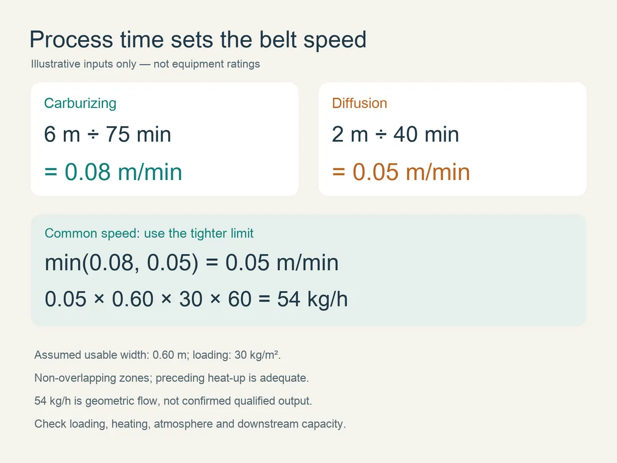
- Carburizing limit: 6 ÷ 75 = 0.08 m/min.
- Diffusion limit: 2 ÷ 40 = 0.05 m/min.
- Both stages use the same speed, so the process-time speed limit is min(0.08, 0.05) = 0.05 m/min, where min means the smaller value.
Serial critical zones must all receive their required time. The most restrictive zone controls the permissible speed; adding the times and taking a single overall average is insufficient.
Recalculate at the limiting speed
At the example's 0.05 m/min:
| Item | Calculation | Comparison with the minimum |
|---|---|---|
| Carburizing residence | 6 ÷ 0.05 = 120 min | 45 min above 75 min |
| Diffusion residence | 2 ÷ 0.05 = 40 min | Exactly meets 40 min |
| Geometric throughput | 0.05 × 0.60 × 30 × 60 = 54 kg/h | Establishes only geometric flow for this loading |
Diffusion is the limiting zone in this example. The 45-minute arithmetic margin above the carburizing minimum does not allow a speed increase, because diffusion would lose its required time first. Whether that additional carburizing residence is acceptable still requires process validation. Loading, heating, atmosphere and downstream capability are also unproven here, so 54 kg/h is not confirmed qualified output.
Why not divide total length by total required time?
Combining the zones gives 8 ÷ 115 ≈ 0.0696 m/min. The combined residence appears to be about 115 minutes, but the diffusion residence at that rounded speed is only:
2 ÷ 0.0696 ≈ 28.7 min, below the assumed 40-minute requirement.
Meeting total time does not mean meeting each critical zone time. Calculate the separate limits and use the most restrictive one.
When should equipment configuration be reconsidered?
If a zone persistently controls speed—for example, the assumed 2 m diffusion zone needing 40 minutes—slowing down gives it sufficient time but also adds residence in longer zones and reduces throughput. Compare:
- Zone-length proportions against required time proportions.
- The effective process-zone configuration.
- Whether a revised process schedule is permissible after validation.
- Whether target output and target case depth can both be achieved.
Persistent mismatch between zone-length ratios and required time ratios is an equipment-configuration issue, not simply a speed-setting issue. Reassess diffusion length or the process plan; this example alone does not prove that the diffusion zone must be lengthened.
Why can the complete line still fall short?
After carburizing, the workpieces may require quenching, washing, tempering and transfer in accordance with product requirements. Quenching develops the required hardened condition through cooling; tempering subsequently adjusts properties through controlled heating. These steps are linked processes, not merely downstream handling accessories. See Bodycote's atmospheric carburizing description.
For the same workpiece and treatment requirements, increased continuous flow raises heating, carbon-supply and downstream workload per unit time. Gas flow, power and cooling capacity must be calculated separately, not all scaled mechanically in direct proportion to output.
| Part of the line | Check when increasing output | Potential limitation |
|---|---|---|
| Heating | Can additional cold workpieces reach temperature at the planned position? | Furnace indication is correct but workpiece heat-up ends farther downstream, reducing effective process time |
| Protective/carburizing atmosphere | Can supply, distribution and control serve the added surface area and load? | Setpoints remain unchanged but carbon supply and uniformity under load are unverified |
| Belt load capability | Permissible hot loading, supports and drive conditions | Cold-load evidence alone does not authorize higher loading at temperature |
| Quenching | Heat input per unit time, liquid-temperature history, circulation/cooling and conveying residence | Temperature keeps climbing during continued feed, or cooling and receiving time are inadequate |
| Washing | Oil carryover, contact time, recirculation treatment and exit condition | Feed rate increases beyond the washing conditions or required cleanliness |
| Tempering | Heat-up, effective holding time, loading and heating capacity | Speed is increased to accept upstream flow, shortening required tempering time |
| Loading, unloading and logistics | Sustained loading arrangement, discharge, container changes and transfer | Temporary piles or frequent stops are required to connect the stages |
This check follows continuous mass flow and each stage's work. Data under the same operating conditions establish which part limits first. Manufacturer literature also identifies heating, atmosphere distribution, synchronized conveying and quench-oil circulation as separate systems; naming these features alone does not prove capacity. See SECO/WARWICK's mesh-belt furnace description.
Stable line output is limited by the first part to reach its constraint. Buffers absorb short fluctuations but do not remove a sustained mismatch in average processing rates. Production scheduling must also use actual startup, shutdown, changeover and accepted-product records, without inventing a fixed utilization or yield factor.
For lines using combustible atmospheres and oil quenching, an output-increase proposal should identify responsibilities and interlocks for atmosphere abnormalities, belt stops, cooling abnormalities and exhaust interfaces. This is a request for engineering verification, not a set of safety settings or an operating procedure.
What must accompany a supplier's hourly-output figure?
First ask: “Which workpiece and carburizing requirement does your hourly figure apply to?” Request the following in one capacity statement.
| Buyer question | Corresponding supplier information | How to assess it |
|---|---|---|
| What is the workpiece and its piece mass? | Steel grade, dimensions/shape, piece mass and incoming condition | Match the purchase requirement; reconcile piece count and mass |
| How is it arranged on the belt? | Orientation, spacing, layers, overlap rules and representative photographs | Distinguish a production arrangement from an ideal fully packed belt |
| What is the loading per square metre? | Actual usable width, workpiece mass per unit area and weighing basis | Recalculate geometric flow using the same arrangement |
| What is the belt speed? | Working speed for that process and load | Distinguish mechanical range from a speed checked against process times |
| How long are carburizing and diffusion, and how much time is available? | Zone boundaries, heat-up boundary and respective residence times | Avoid overall-length substitution; check every stage |
| What are temperature and carbon potential? | Stage settings, records or validation for the steel and target depth | Identify whether higher output relies on a changed process and whether it was reconfirmed |
| What case depth is required and how is it accepted? | Effective-depth target and definition, applicable standard and edition, test method, position and workpiece condition | Compare equivalent quality requirements |
| Has downstream equipment been checked at that output? | Quenching, washing, tempering, handling and logistics capability under the same conditions | Identify the first constraint; obtain missing zone evidence before increasing speed |
If only maximum speed and overall length are supplied, request effective process zones and corresponding times before confirming carburizing capacity. If the provided lengths, speeds and required times fail the calculation, change the speed or proposal; completing a parameter list does not itself resolve the mismatch.
What should the buyer prepare next?
A complete design file is unnecessary for the first discussion. Bring three groups of available information and identify missing items:
- Representative workpieces: photographs or sketches, grade, dimensions, piece mass and normal loading photographs. These establish whether the area-loading assumption is credible.
- Product requirements: target effective case depth, surface/core hardness and testing/acceptance requirements; include existing process records where available. These establish what the calculated time must satisfy.
- Output and equipment conditions: required hourly accepted output, effective lengths, speed and width in the quotation, plus quenching, washing and tempering information. These help locate the constraint in process time, loading or downstream capability.
For an initial check, send the information to Jiangsu Suneng Industrial Furnace Co., Ltd. and identify the request as a continuous-carburizing throughput assessment. Suneng can help organize workpiece, loading, effective process-time and upstream/downstream conditions to identify the first item requiring evidence or adjustment. Process and throughput acceptance still require validation under the agreed operating conditions.
Email: 997518512@qq.com
Telephone: +86-130-5298-6814
Website: Jiangsu Suneng Industrial Furnace Co., Ltd.