
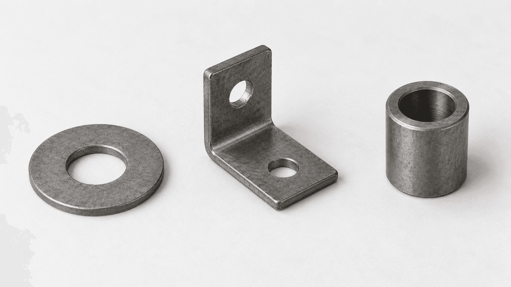
Workpieces & materials
Provide grade, incoming condition, typical and maximum dimensions and unit mass. Clarify the annealing objective or prior quenching condition first.

Loading page…
Loading is taking longer than usual. Please wait or try again.
Retry loadingMatch continuous annealing or tempering to the workpiece and belt loading
For small and medium steel parts that can be spread reliably, the belt connects loading, zoned heating, soaking and controlled cooling. Annealing and tempering of previously quenched parts have separate process routes. Sharing equipment depends on temperature, atmosphere, cooling and changeover conditions.
Standard parts and stamped steel components may suit a belt line when batches and loading are stable. Compare other conveyors or batch furnaces for parts liable to roll or collide, requiring individual positioning or long soaking.
Provide grade, incoming condition, typical and maximum dimensions and unit mass. Clarify the annealing objective or prior quenching condition first.
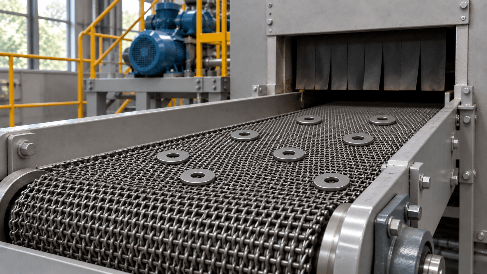
Check belt mesh against part size, orientation, layer depth and load per unit length; control mixing and overlapping.
Point to equipment or select a step to see its location and action
Scroll horizontally for the complete line, or select a step below
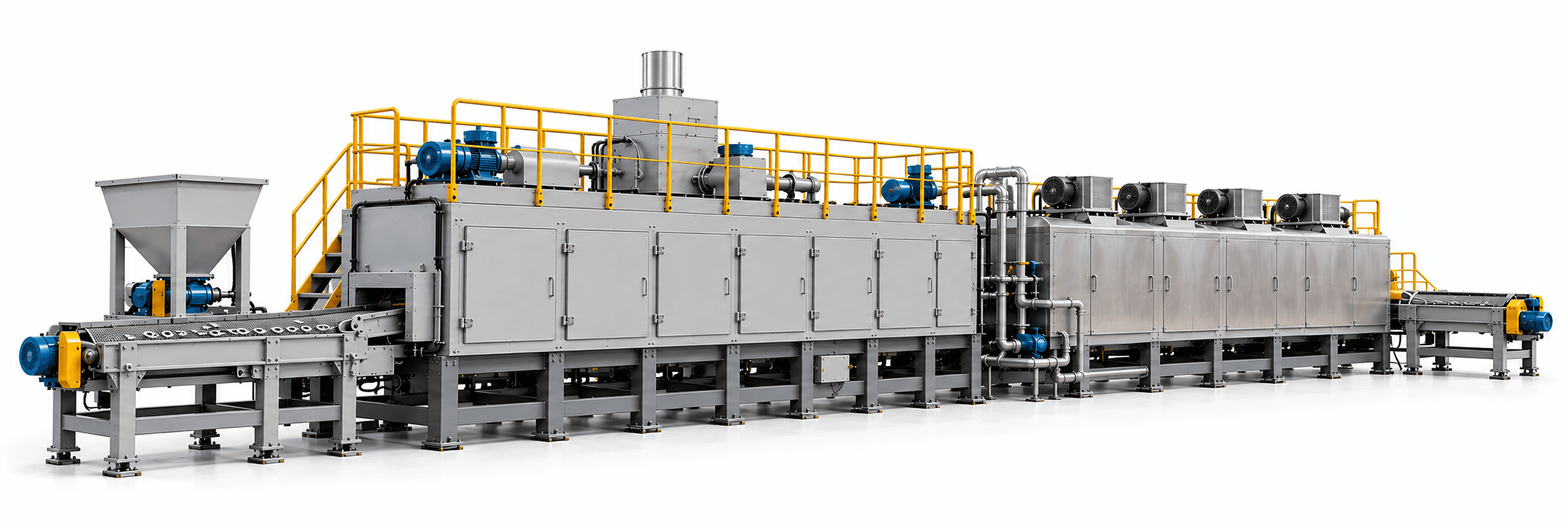
Heat parts for the required annealing type, matching the furnace schedule to loading.
Equipment: Heat & soak
Loading, heating and soaking, controlled cooling and discharge run continuously. Treat annealing and post-quench tempering as separate routes.
Choose the annealing type for the material, initial microstructure and objective. Long soaking or slow cooling, such as spheroidizing, also requires an economic comparison of furnace length, cycle time and other furnace types.
Residence time in a furnace section is not effective workpiece soaking time. Determine the start of soaking using the applicable process specification and through-heating of a representative load.
Highlights identify functional areas. Equipment and layout follow the agreed proposal.
Assess this route separately; it does not map one-to-one to the equipment above.
Confirm prior quenching condition and permitted delay. This route receives already quenched parts; a complete quench-and-temper line also needs quench heating and a quenching-medium system.
Process temperature, load and cycle time jointly determine furnace sections and conveying equipment.
Scroll horizontally to view the complete comparison
| Configuration item | Equipment & interface requirements |
|---|---|
| Feeding and distribution | Select feeding for the part shape; control loading width, depth, overlaps and batch separation. |
| Furnace and temperature zones | Calculate heating method, zone lengths and belt speed from workpiece and belt thermal loads, through-heating and soaking requirements. |
| Belt and supports | Check belt material, mesh and supports against temperature, atmosphere and total load; allow for thermal expansion, tensioning and tracking. |
| Atmosphere and sealing | Select air or protective atmosphere for oxidation, decarburization and cleanliness requirements. Combustible constituents require appropriate purging, monitoring and interlocks. |
| Controlled cooling | Choose the cooling path, sections and discharge temperature for the material and target microstructure. Cooling method and capacity must match belt speed. |
| Control and traceability | Coordinate temperature, belt speed, feeding and utilities. Record recipes, alarms and batch time windows; agree on abnormal belt-stop procedures. |
For shared annealing and tempering equipment, check temperature zones, atmosphere, cooling, line clearance and recipe changeover separately. Maximum design temperature does not replace verification of the working range and workpiece temperature.
Theoretical workpiece mass flow (kg/h) = net workpiece load per unit belt length (kg/m) × steady belt speed (m/min) × 60. Measure net loading using the actual effective width and loading pattern; account for belt and tooling carrying and thermal loads separately. Design capacity must also satisfy through-heating, soaking and cooling. Calculate annual conforming output from effective production hours, actual feeding utilization and yield without deducting the same downtime, empty-belt time or quality loss twice.
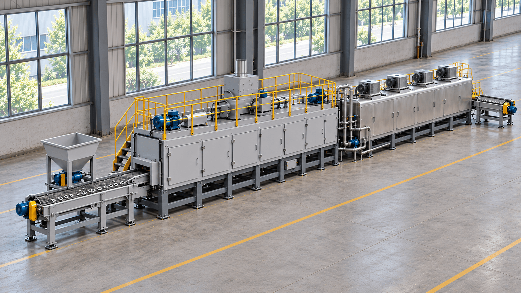
Define equipment, auxiliary systems and site interfaces.
List supplied equipment, auxiliary scope and each party's responsibilities in the technical agreement.
Agree equipment functions, process performance and product verification separately.
Check belt conveying, tracking and tension, loaded operation, interlock alarms and abnormal belt-stop handling.
Check the effective heating zone, temperature measurement and belt speed; verify through-heating, effective soaking and cooling with representative loading.
Inspect hardness, microstructure or mechanical properties for the target process, together with oxidation, decarburization and surface requirements.
Validate representative annealing and tempering recipes separately. For shared equipment, also check line clearance, changeover and batch separation.
Follow the technical agreement for materials, loading, sampling, assessment and responsibilities. Record equipment acceptance and product-quality verification separately.
Review selection, auxiliary equipment and site integration for this process.
Shared equipment for separate batches can be evaluated, but incoming conditions and objectives differ. Confirm working temperatures, atmosphere, cooling, clearance and changeover separately. This tempering route receives quenched parts; a full quench-and-temper line requires its own quenching system.
Width must accommodate the parts, loading pattern and edge clearance. Belt speed must satisfy through-heating, effective soaking and cooling. Section length divided by speed is residence time, not automatically workpiece soaking time.
Compare batch furnaces or other conveying arrangements for long soaking or slow cooling, frequent changeovers, parts prone to rolling or collisions, individual positioning or loads beyond belt capacity. Assess suitability using process cycle, load and target output.
Multiply net workpiece mass per unit belt length by steady belt speed and 60 for theoretical mass flow under continuous steady feeding. Then check heating, soaking, carrying and cooling limits. For shift or annual conforming output, include only empty-belt, changeover, downtime and quality losses not already accounted for.
Start with workpiece and material, annealing or tempering target, output and contact details. Include available dimensions, weights, loading photos, process curves, prior quenching records or site layout. Resolve unknowns during discussion.
Mesh-Belt Annealing & Tempering Line · Project consultation
Tell us about the workpiece, throughput or existing equipment issue. Drawings and detailed parameters can follow.
Prefer to talk first? Contact us directly.
What you will receive