
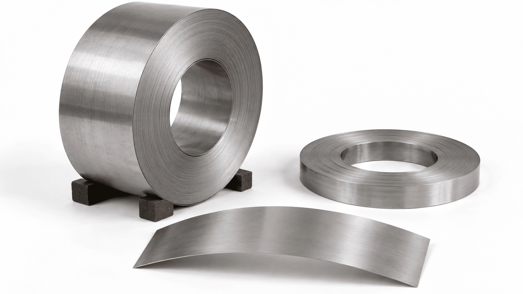
Material and surface targets
Grade, hot- or cold-rolled condition, initial microstructure, oxidation, brightness and subsequent surface-treatment requirements.

Loading page…
Loading is taking longer than usual. Please wait or try again.
Retry loadingMatch the thermal section and continuous line to the strip and surface requirements
For stainless and suitable alloy strip, continuous heating, soaking and controlled cooling coordinate with reel handling, tension and tracking. Confirm grade, incoming condition, microstructure, properties and surface before defining the annealing or solution-treatment temperature path, speed and equipment scope.
The meaning of annealing and solution treatment depends on the material system. Stainless steel commonly uses the term solution annealing. Assess shared equipment from grade, target microstructure and the temperature-time-cooling schedule.
Grade, hot- or cold-rolled condition, initial microstructure, oxidation, brightness and subsequent surface-treatment requirements.
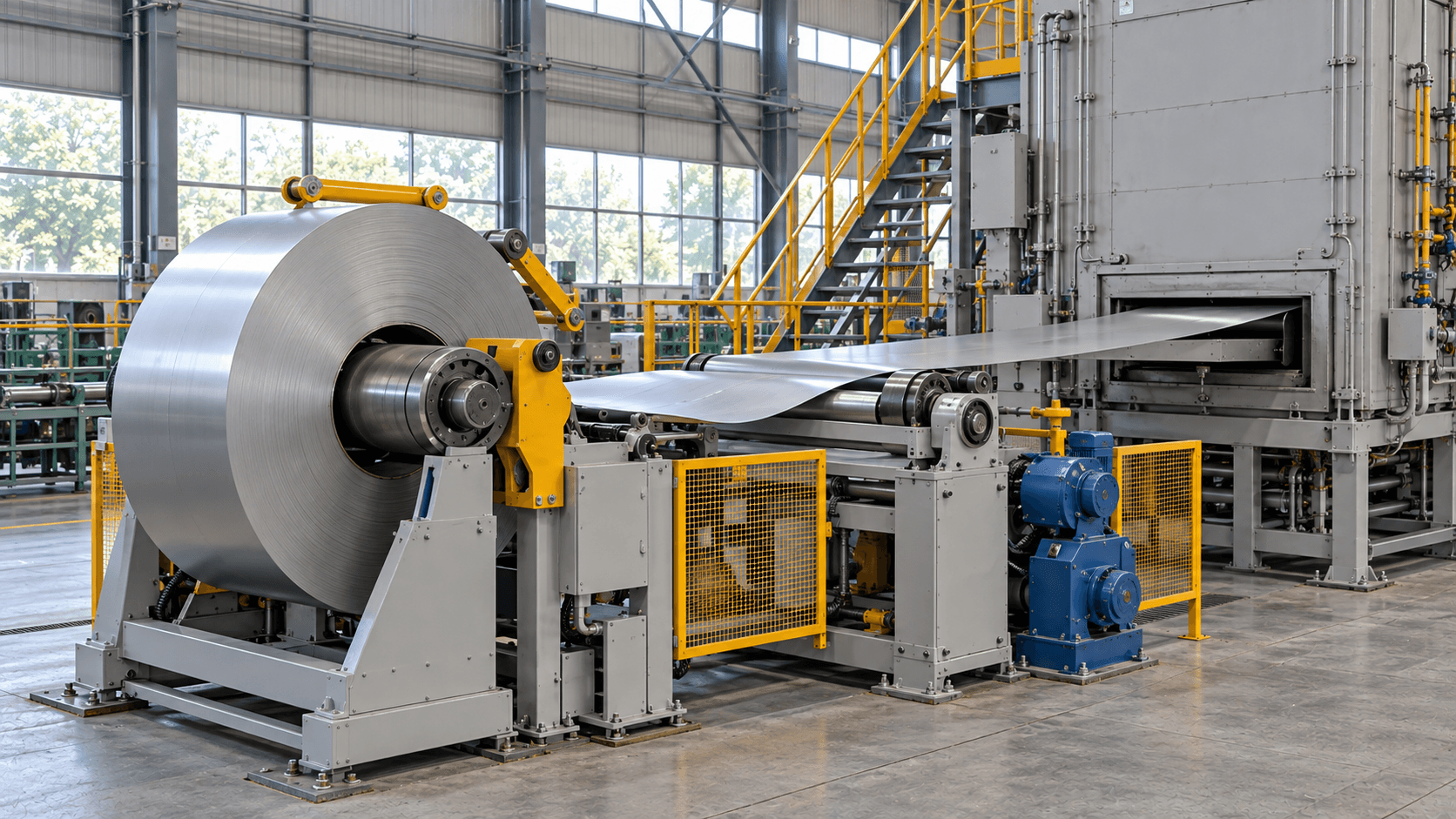
Width, thickness, coil mass and inside/outside diameters; also check edges, joints, supports, tension and threading method.
A coil fitting the uncoiler does not establish compatibility with the whole line. Check width, thickness, joint passage, heating capacity and cooling window together.
Point to equipment or select a step to see its location and action
Scroll horizontally for the complete line, or select a step below
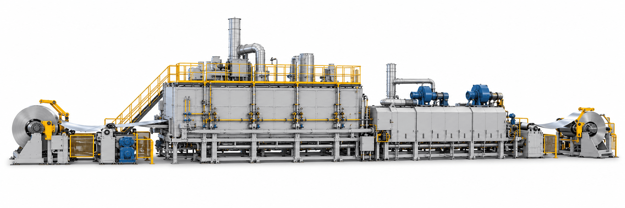
Soak for the selected annealing or solution-treatment process. These are not two mandatory consecutive operations.
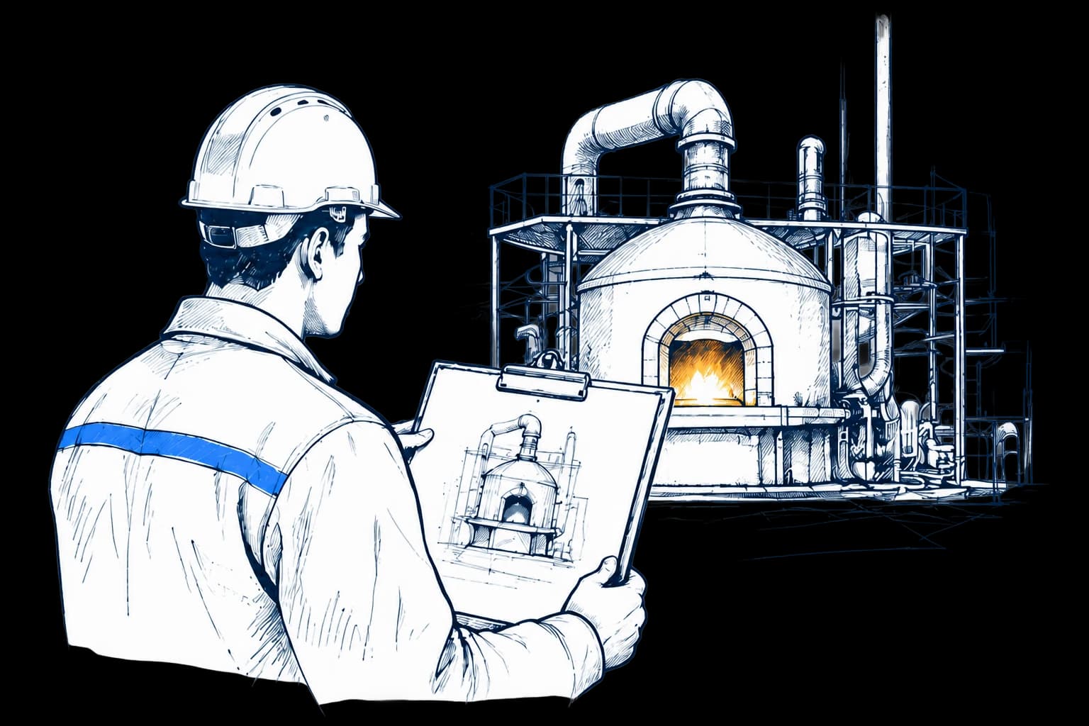
Equipment: Heat-treatment furnace section
Entry conveying, heating and soaking, process cooling and exit handling form the heat-treatment route. Surface targets determine preceding/following operations and atmosphere.
For projects permitting subsequent descaling, pickling or other surface treatment. List pickling, washing, accumulators and reel handling separately in the supply scope. Choose cooling combinations for the material, flatness and downstream operations.
Evaluate furnace type, atmosphere and cooling separately for each route; this does not imply direct changeover on one line. The overall illustration explains interfaces. It does not establish actual lengths, module counts or whether pickling and other equipment are supplied.
Highlights identify functional areas. Equipment and layout follow the agreed proposal.
Assess this route separately; it does not map one-to-one to the equipment above.
For projects with specific oxidation and surface requirements. Determine gas composition, cleanliness, dew point, oxygen content and atmosphere safety systems from the process. Protective atmosphere alone does not guarantee a bright surface.
Heating, cooling and strip travel constrain each other. Do not select equipment solely by maximum furnace temperature or mechanical speed.
Scroll horizontally to view the complete comparison
| Configuration item | Equipment & interface requirements |
|---|---|
| Heating & equalization | Calculate furnace sections from representative grade, thickness, target strip temperature, effective soaking and heat transfer. Record setpoint and actual strip temperature separately. |
| Cooling and surface | Select air, mist, water or protective cooling for the material specification and surface target. Check cooling-start point, exit temperature, water quality, flatness and drying interfaces. |
| Tension and tracking | Check entry/exit tension, support rolls, tracking, accumulators and joint passage together. Define acceleration/deceleration, strip-break and abnormal-stop strategies. |
| Atmosphere and heat source | Design the heat source, combustion/flue gas or protective atmosphere separately. For protective-atmosphere routes, also check sealing, purging, monitoring, discharge and fault interlocks. |
| Temperature measurement & records | Distinguish control-point temperature, furnace uniformity and actual strip temperature. Agree on measurement methods, representative sizes, records and acceptance conditions. |
| Upstream/downstream interfaces | List uncoiling, washing, accumulators, pickling, recoiling, communications, utilities and main-contractor responsibilities individually. Do not assume external operations belong to the thermal-section supply. |
Different thicknesses of the same grade may need different speeds and recipes. Include transitional material from reel changes, joints and product changes in production planning.
Theoretical mass flow (kg/h) = density (kg/m³) × strip width (m) × thickness (m) × speed (m/min) × 60. Sum annual conforming capacity across representative sizes using effective operating hours and yield; do not deduct downtime or coil changes twice. Furnace residence time is effective length divided by speed. Separately check effective soaking after the material reaches target temperature.
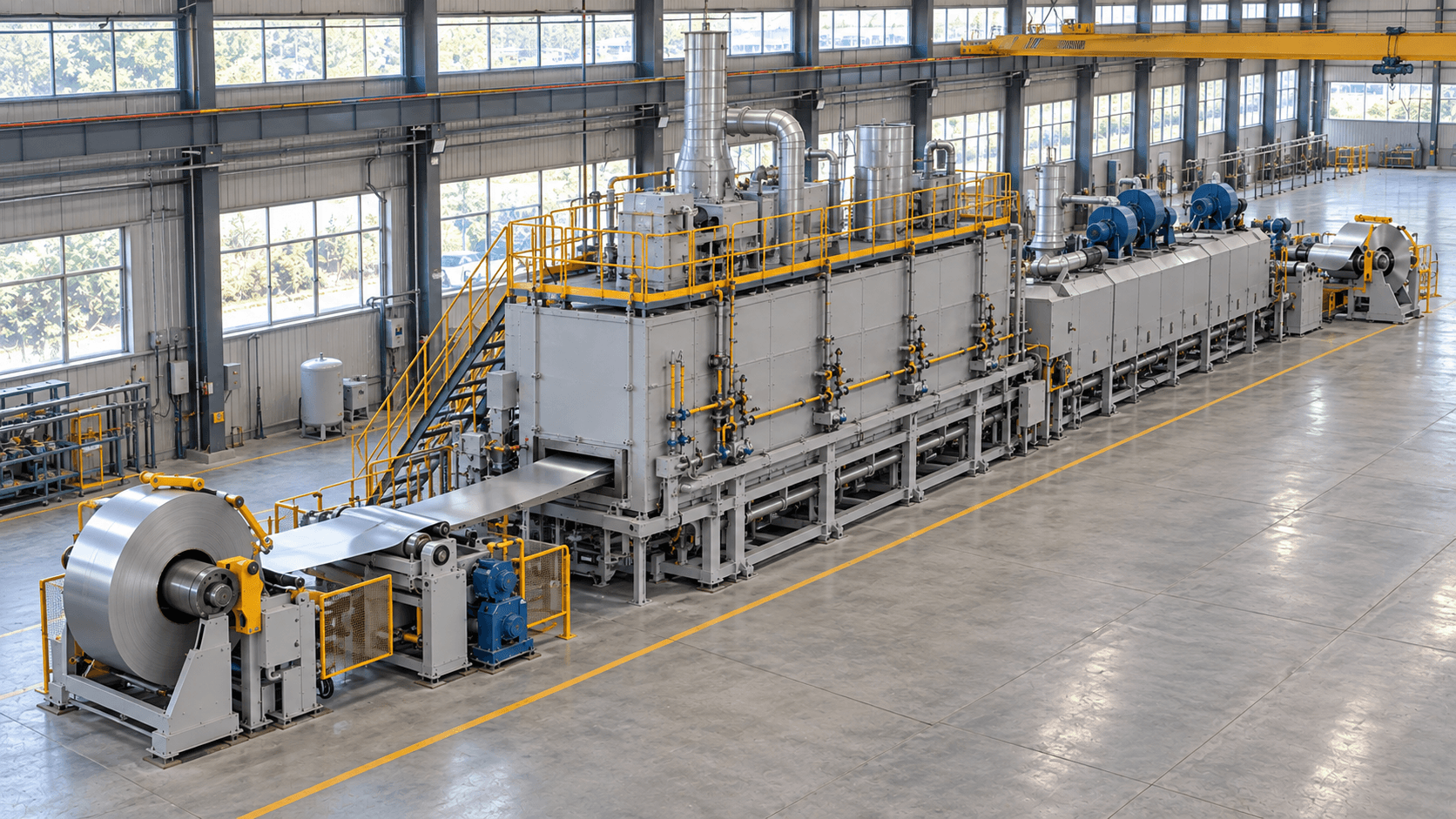
Distinguish public project experience from this supply list; do not assume preceding/following operations fall under one contract.
List the equipment, supply scope and responsibilities in the technical proposal.
Agree equipment functions, process performance and product verification separately.
Check threading, tension, tracking, accumulators, acceleration/deceleration, interlocks and abnormal strip-stop strategies.
Validate temperature path, strip-temperature measurement, effective soaking and cooling under representative conditions. Control temperature and strip temperature are not interchangeable.
Inspect microstructure, mechanical properties, surface and flatness for representative grades and thicknesses. Agree on inspection items and sampling under the adopted standard.
Verify equipment functions, process conditions and product results separately. Without representative material and acceptance criteria, temperature-control data cannot establish product conformity.
Define conditions and responsibilities separately for equipment acceptance and product inspection. Agree representative materials, loading, sampling and pass criteria.
Review selection, auxiliary equipment and site integration for this process.
Assess shared equipment by material family and product window, but establish separate temperature, time, atmosphere and cooling recipes and validate changeover, clearance and upstream/downstream capacity.
Thickness, target strip temperature, effective heating length, soaking time, cooling capacity, tension and adjacent operations jointly determine speed. It cannot be guaranteed independently.
Furnace temperature describes the equipment environment. Material condition also depends on heat transfer, speed, thickness and loading. Measure or validate strip temperature using the agreed method.
Materials differ in required cooling-start point, rate, flatness, surface and exit temperature. Stages enable combined control, but validate results under representative conditions.
First allocate mechanical, electrical, utility, flue-exhaust, foundation, communications, installation, commissioning and acceptance responsibilities between equipment subcontractor, owner and main contractor.
No. Incoming cleanliness, material, gas composition, dew point, oxygen content, temperature path, sealing and cooling all affect the result. Validate surface condition with representative operating conditions.
Those parameters apply to specific grades, sizes and equipment responsibilities; they are not universal capabilities. Recalculate each project from width, thickness, temperature path, surface and output requirements.
Strip Annealing & Solution Treatment Line · Project consultation
Tell us about the workpiece, throughput or existing equipment issue. Drawings and detailed parameters can follow.
Prefer to talk first? Contact us directly.
What you will receive