

Fixtures are auxiliary structures used to support, locate or carry workpieces. They affect load capacity, support, heating and transfer. To assess loading racks and fixtures, Jiangsu Suneng Industrial Furnace Co., Ltd. recommends checking workpiece weight, fixture self-weight, load distribution, support points, spacing, shielding from heat, lifting or transfer routes, and acceptance records together. Incomplete information can reveal gaps, but it cannot support a guarantee of “no distortion.”
Why fitting inside the chamber is not enough
Chamber dimensions only show whether an object can enter a space. They do not establish:
- Whether the rack and fixtures can carry the workpieces, their own weight and loads arising during movement;
- Whether support points are suitable or whether self-weight, heating and cooling could cause harmful distortion;
- Whether fixtures, workpieces and adjacent parts obstruct heating, circulation, temperature measurement or atmosphere flow;
- Whether the rack can safely enter, locate, exit and connect with cranes, forklifts, tracks, roller conveyors or downstream equipment;
- Whether final acceptance evaluates equipment condition or product results obtained with actual fixtures and workpieces.
Fixtures should therefore be treated as a separate engineering decision, with their requirements finalized alongside the furnace, hearth, conveying system and acceptance conditions.
Calculate the total load before comparing rack capacity
The basic relationship is:
Total loaded weight = workpiece weight + fixture self-weight.
Fixtures do not count as conforming product output, but they still have to be heated inside the furnace. They are both a structural load and a thermal load. Under otherwise comparable conditions, fixture mass, material, initial temperature and quantity change the total heat that must be absorbed. Heavy fixtures may use more heating capacity, lengthen heating or stabilization, affect the batch cycle and increase energy use per unit of conforming product. This does not mean that reducing fixture weight reduces energy consumption by the same percentage. The furnace structure, process curve, loading and heat losses still have to be considered.
Here, “sensible heat” means heat absorbed as workpiece or fixture temperature rises, excluding heat required for phase transformations. “Approximately equal average specific heat” means that, over the temperature range being compared, equal masses of the two materials require approximately equal heat for the same temperature rise.
If only the sensible heat of the workpieces and fixtures is compared, their average specific heat is approximately equal, and their initial and target temperatures are approximately the same, a simple relationship can estimate the fixture contribution to the load’s thermal demand:
Fixture share of total load sensible heat ≈ fixture mass ÷ (workpiece mass + fixture mass).
For example, a batch containing 2 t of workpieces and 0.8 t of fixtures gives a fixture share of approximately 0.8 ÷ 2.8 ≈ 28.6% under those assumptions. This is not 28.6% of total furnace energy consumption: it excludes heat stored in the furnace structure and lining, heat losses, flue-gas losses, door-opening losses, circulation and motor energy. The mass ratio also cannot be applied directly when specific heats differ significantly, initial or final temperatures differ, or phase transformations occur.
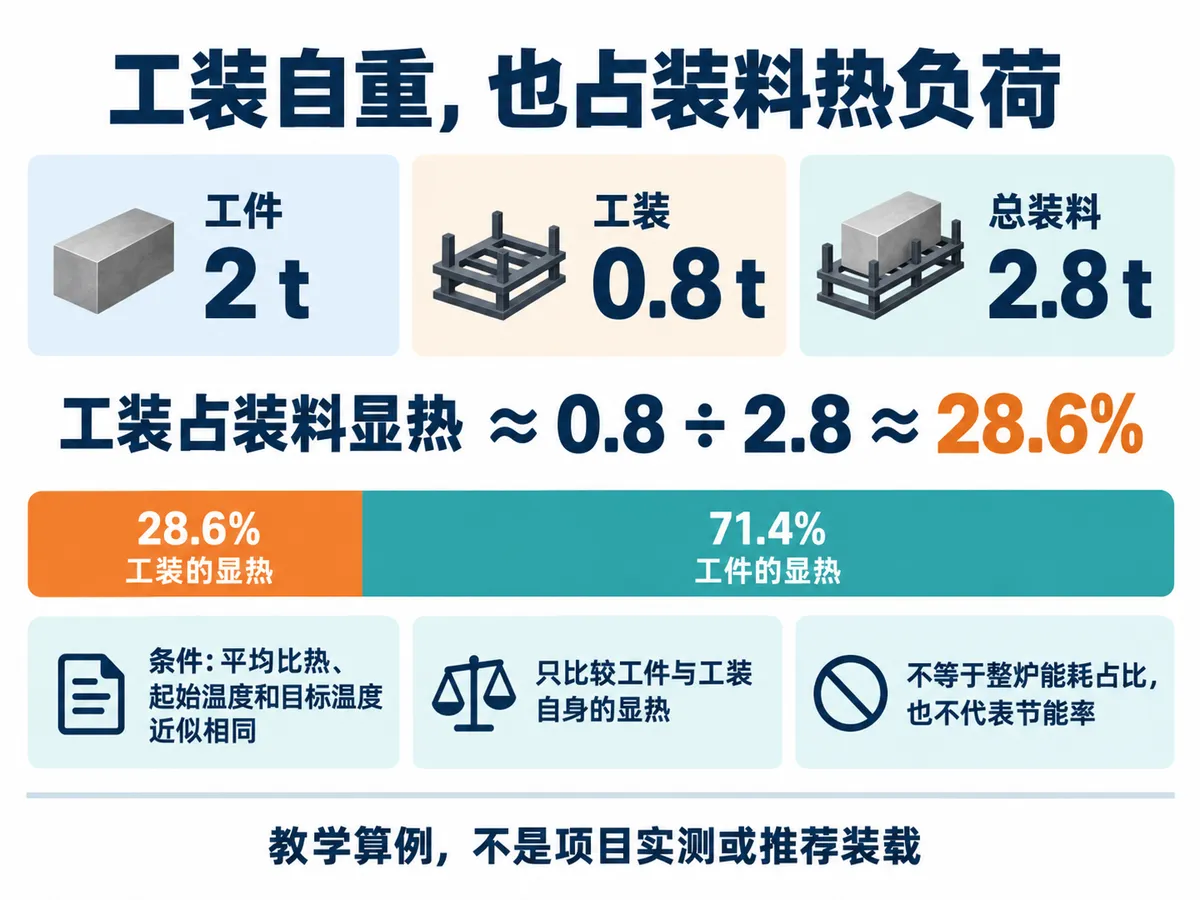
Illustrative calculation comparing only the workpieces’ and fixtures’ sensible heat, with approximately equal average specific heat, initial temperature and target temperature. The 28.6% figure is neither a share of total furnace energy nor an energy-saving rate. Diagram labels are in Chinese; the calculation and its conditions are explained above in English.
This relationship helps when comparing quotations. If two suppliers both specify “2 t of product per batch,” also ask each to state the fixture self-weight per batch and its share of the total load. A higher fixture share means more heating capacity goes into non-product mass; heating demand and cycle time may increase. Fixtures can also affect the net weight of conforming product that fits within the same chamber.
This is why capacity calculations must exclude fixture weight from conforming product output while equipment design must still include it. Fixtures add no product tonnage, but they use real load-carrying and heating capacity.
Total weight is only the starting point. Also check:
- Piece count, individual workpiece weight and variation between batches;
- Workpiece orientation, stacking and support-point positions on the rack;
- Whether the load is concentrated on a few supports or is distributed unevenly;
- The loads carried by the rack, hearth, wheels, tracks, drives and lifting tools respectively;
- Whether forces differ between cold loading/unloading, hot operation and transfer after discharge.
Rated load capacity must not be quoted without its load distribution and operating conditions. Retain load lists, fixture drawings and load-capacity calculations in the project documents. Values must come from the design and jointly confirmed documentation, not a universal tonnage applied across projects.
Supports and spacing must serve heating and product quality
Rack supports, crossmembers, uprights and locating features directly affect exposure to heat and constraints on workpiece distortion. At minimum, establish:
- Where the workpiece is supported and whether that support creates local shielding or uneven heating;
- Whether spaces between workpieces and between workpieces and fixtures meet loading, thermal-cycle, temperature-measurement and operating needs;
- Whether fixtures obstruct circulation paths, measurement points or the effective heating zone of burners or heating elements;
- Whether changes in support or contact during heating, soaking, cooling and discharge could make the workpiece unstable;
- Whether fixture material, structure and maintenance condition are compatible with temperature, atmosphere, cooling and cleanliness requirements.
No fixed spacing is prescribed for all equipment, and reduced shielding is not a guarantee of temperature uniformity. The qualified working zone is generally smaller than the geometric chamber space. Design checks need the workpiece, fixture and loading drawings together.
For long shafts, rods, thin plates, long unsupported spans or other workpieces whose stiffness may fall substantially at elevated temperature, stable placement when cold does not establish that the same shape will be retained when hot. Load-bearing stiffness may decrease while self-weight remains. The number and position of supports and the span between them therefore affect self-weight deflection and distortion risk. Check support design against material, temperature, geometry and process condition rather than applying one spacing to every project.
Do not leave fixture and transfer interfaces to site improvisation
Moving a rack from preparation into the furnace, and then to discharge or downstream equipment, may involve cranes, forklifts, tracks, rollers, lifting attachments or manual assistance. For each interface, define:
- Who supplies the loading rack, lifting attachments, discharge rack and connectors;
- Direction, space and travel-limit conditions during entry, positioning, withdrawal and handover;
- The full-load center of gravity, uneven loading and measures against overturning;
- Hot-transfer temperature, waiting time, personnel separation and response to abnormal stops;
- Responsibility for foundations, tracks, lifting equipment, downstream receiving equipment and site utilities.
The technical agreement should separately define supply and interface responsibilities for loading racks, discharge racks, lifting attachments, transfer before and after the furnace, and subsequent equipment. Otherwise, even an operable furnace may encounter loading, unloading or handover interfaces that do not connect properly on site.
Use the actual fixtures for a three-step verification
Step 1: Check the documents
Prepare workpiece drawings or photographs, material and individual weight, loading lists, rack and fixture drawings, support and spacing details, lifting or transfer routes, hearth and track information, and quality and acceptance requirements. Mark each missing item for confirmation.
Step 2: Check movements while cold
Without heating, verify safe rack entry, positioning, withdrawal and handover. Check the full-load center of gravity, travel limits, interference, jamming and space for personnel. A successful cold movement check establishes only part of the geometry and motion requirements; it does not replace hot validation.
Step 3: Validate with actual fixtures and loads
Using the agreed process curve and loading arrangement, check temperature, circulation, records and product inspection results. Observe workpiece condition at critical supports, shielded positions and transfer interfaces. Acceptance must specify the test condition, measurement points, records, sampling and evaluation method. If an abnormality occurs, records should allow it to be traced to changes in fixtures, loading, process, equipment or site interfaces.
Validation can reduce overload, shielding and distortion risks. It cannot guarantee distortion-free parts when information, operating conditions or inspection are insufficient. Record design targets, test results and batch-production results separately.
Four commonly underestimated fixture issues
- Providing chamber dimensions without a loading diagram. Dimensions alone do not describe supports, uneven loading, thermal circulation or transfer space.
- Counting workpiece weight but ignoring fixtures. Fixture weight and load distribution change the forces acting on the hearth, tracks and drives.
- Making fixtures denser to save space. Excessive density can obstruct heating, circulation and measurement, and reduce the safety margin for loading and unloading.
- Assuming cold entry and exit prove freedom from distortion. Distortion also depends on material, process, support, heating and cooling, and must be assessed using actual fixtures and loads.
Prepare load, support and transfer information before procurement
Prepare workpiece drawings or photographs, material grades, maximum and usual dimensions, individual and batch weights, fixture and rack drawings, support locations and placement, a loading sketch, lifting and transfer conditions, hearth and track information, process curves, atmosphere or cooling conditions, acceptance measurement points and product evaluation methods. For a retrofit, also provide records of existing fixture distortion, jamming, uneven loading and maintenance.
Jiangsu Suneng Industrial Furnace Co., Ltd. can use these documents for an initial assessment of rack and fixture load limits, missing support or spacing information, heating-obstruction risks, transfer interfaces and required validation items. This does not replace structural design, strength calculations, heat treatment process qualification, personnel-safety assessment, regulatory requirements or the signed technical agreement. Reducing distortion risk is not a promise of zero product distortion.
To request an initial document review, provide the workpiece, fixture and site-interface information above and identify the request as “Loading-rack and fixture load-capacity review.”
Telephone: +86-130-5298-6814
Email: 997518512@qq.com
Website: https://www.jssngyl.cn
Basis and scope: The judgments in this article rely on general heat-transfer principles, structural load relationships, equipment interfaces and procurement/acceptance management logic. Unverified historical project documents are not presented as public factual evidence. The 2 t + 0.8 t example is illustrative, not an actual project or a recommended load. Structural, process and acceptance conclusions must be based on formal project documents.